Full Stack Electronics · Stage Two · Experiment 2

Experiment 2: The 555, Unpacked

Build the timer from separate blocks, then see why its output needs a driver.

In Experiment 1, you built a blinker and measured its output and capacitor voltage. Now you build a similar timer from two chips, resistors and transistors. You can probe the connections between its blocks and see how they work together.

We connect and check the blocks one at a time. Experiments 3 to 11 then rebuild the comparators, the divider and the latch from transistors and measure each one.

You will need

Use a second breadboard and a second set of timing parts, so the reference 555 stays assembled. The timing resistor and capacitor values match Experiment 1. Individual components can still differ within their tolerances.

Follow the blocks from left to right

Inside the 555 timer, five functional blocks charge and discharge an external timing capacitor and switch the output. In this experiment, you rebuild those blocks on a breadboard and measure what each one does.

The schematic grows with the breadboard. Each new stage appears beside the existing parts, which the figures show pale. We build the divider, the comparators and the latch first. Then we add the two branches on the right: the discharge transistor, which completes the timing loop, and the output driver, which lights the LED.

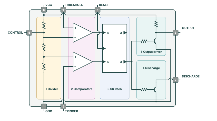
A voltage divider produces two reference voltages. A pair of comparators, grouped as one block, compares the capacitor voltage with those references. A latch stores whether the capacitor should charge or discharge. A discharge transistor switches the capacitor's discharge path, and an output driver supplies current to the LED.

Five functional blocks of the discrete 555: divider, comparators, SR latch, discharge and output driver. The final PCB output uses Q19 with a 4.7 kilohm collector pull-up R21. Q̅ drives Q19 through R14 and the discharge transistor Q20 through R15, each 10 kilohms.
Figure 2-1: The timer's five functional blocks: divider, comparators, latch, discharge transistor and output driver. This overview shows the later transistor timer, in which Q̅ drives both branches. Our IC build uses Q for the output driver and Q̅ for the discharge transistor. Follow the stage wiring below.

A functional copy

We rebuild the timing loop shown in the NE555 datasheet. The blocks sit spread out on a breadboard, so you can measure what happens between them. This experiment uses comparator and logic chips. Later experiments build those blocks from transistors, and Experiment 13 adds the reset input.

1. Build the voltage divider

Figure 2-1 starts with the divider at the left. The divider gives the timer two fixed voltages to compare with the capacitor voltage. I want you to measure these first, while the board holds only three resistors and the supply wiring.

Three equal resistors share the voltage

A voltage divider is a chain of resistors connected across a supply. When nothing else draws significant current from the junctions, the same current flows through all three resistors. Equal resistances therefore have equal voltage drops: each takes one third of the supply voltage.

Count from ground upwards. The first junction is one resistor above ground, so it sits at ⅓ of the supply. The next junction is two resistors above ground, so it sits at ⅔ of the supply. At 5.00 V, expect about 1.67 V and 3.33 V. The equal resistors set these ratios. We use 4.7 kΩ for each.

Disable the supply before changing connections

Disable the power supply outputs before you add, move or remove a component or test jumper. If a power supply output enters constant-current mode, or a part becomes hot, disable the outputs. Then check the wiring. Connect the electrolytic capacitor's striped negative lead to ground. Connect the oscilloscope ground clips only to ground. A ground clip on a signal or on the positive rail can short that point to ground.
  1. Prepare the rails with the supply disconnected. Set power supply output 1 to 5.00 V with a 50 mA current limit. Leave the output disabled. Connect its positive terminal to the top red rail at column 1. Connect its negative terminal to the bottom blue rail at column 1. Join the top and bottom red rails with a red jumper at column 32. Join the top and bottom blue rails with a blue jumper at column 33. Check continuity along every rail section you use. Check that the red and blue rails have no short between them.
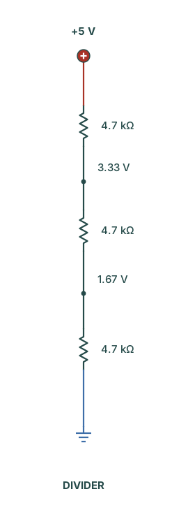
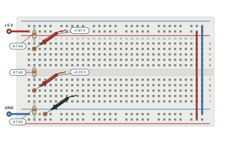
  2. Add only the three divider resistors. Fit the first 4.7 kΩ from the top blue rail into 2a. Fit the second 4.7 kΩ across the centre gap from 2e to 2f. Fit the third 4.7 kΩ from 2j to the bottom red rail. The chain now runs +5 V → 4.7 kΩ → upper reference → 4.7 kΩ → lower reference → 4.7 kΩ → ground. “Upper” and “lower” name the voltages: the upper reference sits lower on the drawing.
Stage 1 schematic: three equal 4.7 kilohm resistors from plus 5 volts to ground, with reference junctions at 3.33 and 1.67 volts. First breadboard stage: only supply links and three 4.7 kilohm resistors in column 2. Each resistor is labelled 4.7 kilohms. Copper-coloured rings mark the lower reference at 2b, about 1.67 volts, and the upper reference at 2h, about 3.33 volts with a 5 volt supply. Two small angled red multimeter probes show the two measurement positions at 2b and 2h. An angled black probe touches the bottom blue rail. Labels show the expected voltage at each reference.
Figure 2-2: The divider schematic and its breadboard layout. Each resistor is 4.7 kΩ. Keep the black probe on ground. The two red probes show two positions for one probe. Measure the lower reference at 2b. Then move the red probe to the upper reference at 2h. Expect about 1.67 V and 3.33 V with a 5 V supply. Click to enlarge.

Check the divider voltages

The divider is now assembled. Before you connect anything to its two references, check that it divides the supply as expected. Use the multimeter to measure the supply, then each junction relative to ground. These three readings show whether the next block receives the reference voltages it needs.

  1. Measure the supply first. Connect the black probe's plug to the multimeter socket labelled COM. Connect the red probe's plug to the socket marked V. Some meters label it V/Ω, because it also measures resistance. Select DC volts, the setting for a steady voltage such as this supply. The dial or button usually shows a V with a solid line above a dashed line. The display shows the voltage at the red probe tip relative to the black probe tip. Enable power supply output 1. Hold the black probe on the bottom blue rail. Touch the red probe to the bottom red rail. Record the supply voltage.
  2. Measure both references. Keep the black probe on ground. Touch the red probe to 2b for the lower reference. Then touch it to 2h for the upper reference. Record both readings. Compare the lower reading with one third of your measured supply, and the upper reading with two thirds of it.

Small differences are normal, because the resistors have tolerances. If either reading is near zero or near the full supply, disable power supply output 1 and check the chain and the rail links. Holes a–e in each numbered column connect together. Holes f–j in the same column form a separate group. The two leads of a resistor must reach different groups.

Before you add the next block, you should have two steady reference voltages, about 1.67 V and 3.33 V. Disable power supply output 1 and leave the divider in place.

2. Add the comparators

The divider gives two steady references, about 1.67 V and 3.33 V. The comparators use them to detect two conditions. TRG (trigger) below 1.67 V starts charging, and THR (threshold) above 3.33 V starts discharging. The two comparators in the LM393 make these comparisons.

In our timer, TRG and THR both watch the same timing capacitor. Each comparator sends its result to the latch, which we add next.
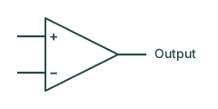
What a comparator does

Comparator symbol: a triangle pointing right. The + input sits at the upper left, the − input at the lower left, and the output at the right-hand tip.
Figure 2-3: The + and − symbols mark the two signal inputs. The chip’s supply pins are separate.

A comparator compares its + and − inputs. With the pull-up resistor described below, its output is high when + is higher than −, and low when + is lower than −. Its output changes whenever the two inputs swap order, and keeps its level while their order stays the same.

Use the LM393 pinout in Figure 2-4 to identify the supply pins, inputs and outputs. The breadboard drawing turns the chip so its notch faces left.
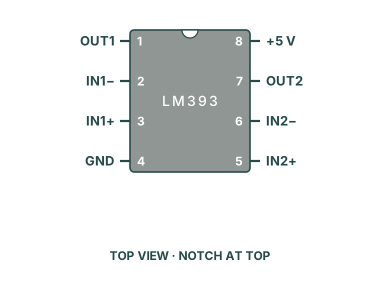
LM393 top-view pinout with numbered inputs, outputs and supply pins, notch at the top.
Figure 2-4: LM393 pinout. Match the pin numbers, even when you turn the chip on the breadboard.

Why the comparator outputs need resistors

Each LM393 open-collector output contains a transistor that can pull its pin low. When that transistor is off, a pull-up resistor connects the pin to +5 V. We fit one 10 kΩ pull-up to each output, so each output gives a defined high as well as a low.

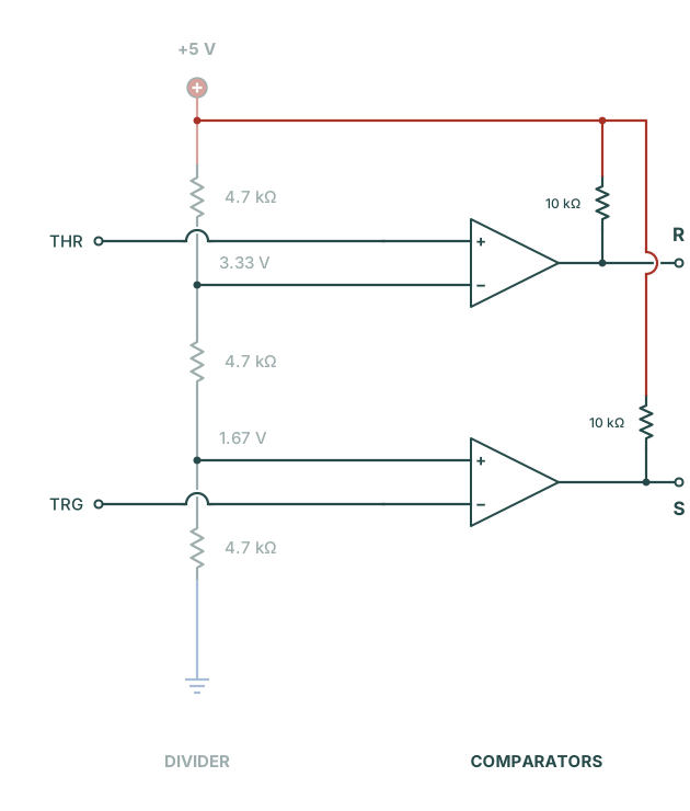
The references are ready, and the pull-ups give each output a clear high or low. Keep the divider in place, and add the LM393 and its two pull-ups as Figure 2-5 shows. Connect the reference inputs now. Leave TRG and THR free, so you can test each comparator before you fit the timing capacitor.
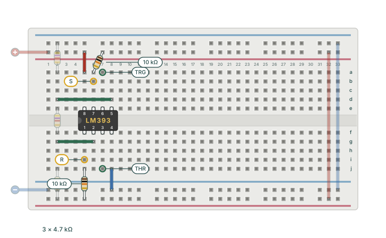
  1. Add and power the LM393. Disable power supply output 1. Insert the LM393 across the centre gap in columns 5–8, notch facing left. Connect pin 8 to +5 V with a red jumper from 5a to the top red rail. Connect pin 4 to ground with a blue jumper from 8j to the bottom blue rail.
  2. Connect the two references. Connect the upper reference to pin 2 (−) with a jumper from 2g to 6g. Connect the lower reference to pin 5 (+) with a jumper from 2d to 8d. Leave the divider where it is.
  3. Add the output pull-ups. Fit one 10 kΩ resistor from the top red rail into 6a (pin 7). Fit the other 10 kΩ resistor from 5j (pin 1) to the bottom red rail.
  4. Identify the inputs. THR is pin 3 (+), at 7j. TRG is pin 6 (−), at 7a. Figure 2-5 marks both holes. Both inputs connect to the timing capacitor later.
Stage 2 schematic: the same divider is muted at the left. Two comparators and their separate 10 kilohm pull-ups are added to its right. THR and TRG come in from the left edge, and their wires hop over the divider. The threshold comparator compares THR with the upper reference and outputs R. The trigger comparator compares TRG with the lower reference and outputs S. Second breadboard stage: the existing divider and rail links are muted. The new LM393, power wires, reference wires and two individually labelled 10 kilohm pull-ups are highlighted. TRG marks pin 6 and THR marks pin 3. Yellow markers identify S at output pin 7 and R at output pin 1. Both signal inputs are unconnected in this drawing.
Figure 2-5: The schematic and breadboard both grow with the LM393 comparators. Pale components stay in place. Coloured parts and wires are new. TRG marks the trigger input at pin 6, and THR marks the threshold input at pin 3. Yellow markers identify the outputs: S (set) at pin 7 and R (reset) at pin 1.

Test the comparators

The LM393 now has its references and pull-ups. Keep these tests near room temperature and at or below 3.40 V. The original LM393 does not accept every voltage up to its positive supply as a valid comparison input. At a 5 V supply, TI specifies an input range up to 3.5 V at 25 °C. Across the full rated temperature range, the limit is 3.0 V. Our 3.33 V threshold is therefore a room-temperature bench demonstration. TI does not guarantee this circuit across that full temperature range.

Keep the board on power supply output 1 at 5 V. Use power supply output 2 for the test voltage, in independent mode (each output set on its own, with no series or parallel tracking selected). Connect the negative terminal of power supply output 2 and the multimeter's black probe to the bottom blue rail.

Test the trigger comparator first. Connect the positive terminal of power supply output 2 to TRG at 7a. Enable power supply outputs 1 and 2, and measure S at 6b with the multimeter. At 1.50 V, below the 1.67 V reference, S should read near 5 V. At 1.80 V, above the reference, S should read near 0 V.

Then test the threshold comparator. Disable power supply outputs 1 and 2. Move the output 2 test lead to THR at 7j. Enable both power supply outputs again, and measure R at 5i with the multimeter. At 3.20 V, below the 3.33 V reference, R should read near 0 V. At 3.40 V, above the reference, R should read near 5 V.

After the tests, disable power supply outputs 1 and 2, and disconnect power supply output 2 from the board.

3. Add the latch

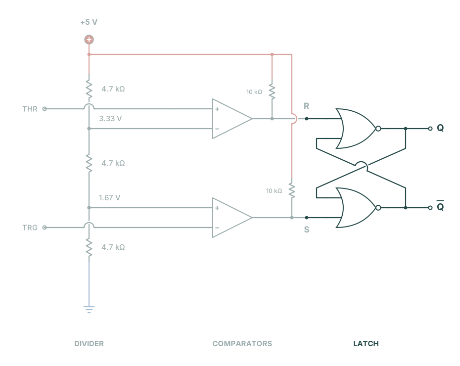
Each comparator output switched at its reference in the tests above. Later, both comparator inputs connect to the timing capacitor. Below 1.67 V, the trigger comparator makes S (set) high to start charging. Above 3.33 V, the threshold comparator makes R (reset) high to start discharging. Between these two limits, S and R are both low (near 0 V), and neither comparator tells the circuit to change state.

That is why the timer needs a latch: a circuit that remembers its last state. While S and R are both low, the latch keeps the capacitor charging if it was charging, or discharging if it was discharging. The next comparator output to go high changes that state.

Two NOR gates make a memory

A NOR gate follows one rule: its output is high only when both inputs are low. Here, low means near 0 V and high means near +5 V. We write these as 0 and 1. The CD4001B contains four NOR gates, and we use gates A and D.

In this latch, each gate's output feeds an input of the other gate. These crossed wires provide feedback: each output helps hold the other gate's state. The four pictures show S going high and then low, followed by R going high and then low. Each picture shows the signals after the gates settle.

1 = high (near +5 V) · 0 = low (near 0 V)
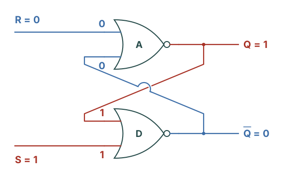
1. SET: raise S to 1

Set: S is 1, R is 0. Gate D has inputs 1 and 1, making Q̅ 0. Gate A has inputs 0 and 0, making Q 1. Q feeds a 1 back to D.

S rises → Q̅ falls → Q rises. D has a high input, so its output is low. A now has two low inputs, so its output is high.
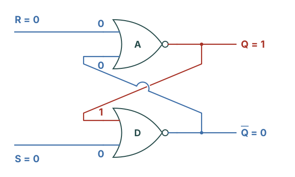
2. HOLD: return S to 0

Hold after set: S and R are both 0. Q remains 1 and feeds gate D, keeping Q̅ at 0. Q̅ feeds gate A. A has two low inputs and keeps Q at 1.

Q stays 1. Follow its high back into D: it keeps Q̅ low. Follow Q̅ back into A: two low inputs keep Q high.
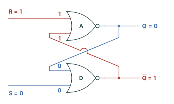
3. RESET: raise R to 1

Reset: S is 0, R is 1. Gate A has two high inputs, making Q 0. Gate D has two low inputs, making Q̅ 1. Q̅ feeds a 1 back to A.

R rises → Q falls → Q̅ rises. A has a high input, so its output is low. D now has two low inputs, so its output is high.
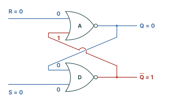
4. HOLD: return R to 0

Hold after reset: S and R are both 0. Q̅ remains 1 and feeds gate A, keeping Q at 0. Q feeds gate D. D has two low inputs and keeps Q̅ at 1.

Q stays 0. The high on Q̅ keeps A's output low. That low feeds D, whose two low inputs keep Q̅ high.
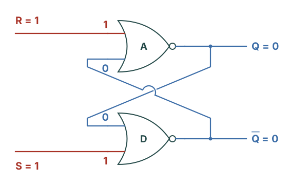
Figure 2-6: Two NOR gates remember the last change. Compare pictures 2 and 4: the same inputs (S = 0, R = 0) hold different outputs, because the feedback keeps the previous state. Dots mark connections. The semicircular jump shows where one wire crosses the other without a connection. Q̅ is the second output.
What if S and R are both high? Invalid combination: S and R are both 1. Each NOR gate has a high input, forcing both Q and Q̅ to 0.

Both gates have a high input, so both outputs become 0. Avoid this combination. If S and R then fall together, the final stored state is unpredictable.

The latch needs power to keep its state. At power-up, apply set or reset to give it a known state.

In our timer, the trigger comparator supplies S and the threshold comparator supplies R. Between the two voltage limits, both are low, so the latch holds its state. Q̅ controls the discharge transistor, which we add next. When Q̅ is high, the transistor is on and the capacitor discharges. When Q̅ is low, the transistor is off and the capacitor charges.
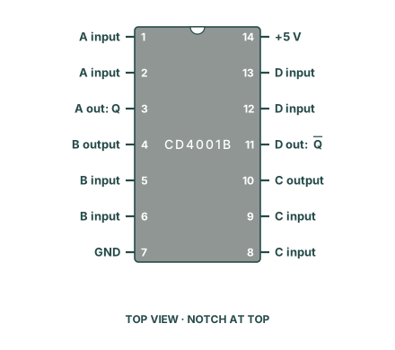
CD4001B top-view pinout. Gates A and D form the latch. Gates B and C are unused. The notch is at the top.
Figure 2-7: CD4001B pinout. A and D mark the two NOR gates in the latch. B and C stay unused.
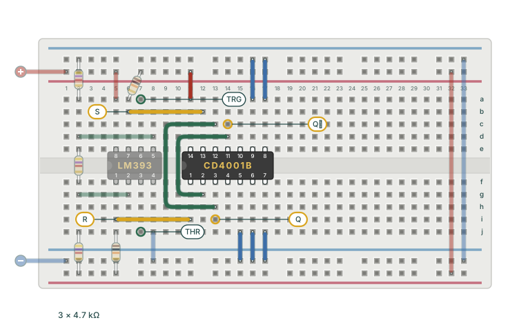
Stage 3 schematic: divider and comparators keep their positions and are muted. Two cross-coupled NOR gates connect to R and S. Q and Q̅ are labelled at their outputs. The CD4001B sits across columns 11 to 17, notch left. Previous divider and comparator parts are muted. Yellow wires labelled S and R connect the comparators to the CD4001B. S runs from LM393 pin 7 at 6b to CD4001B pin 13 at 12b. R runs from LM393 pin 1 at 5i to CD4001B pin 1 at 11i. Green feedback wires on the left of the CD4001B connect pin 3 to pin 12 and pin 11 to pin 2. Yellow markers identify Q at 13i and Q̅ at 14c. Supply wires and grounds for unused inputs are shown.
Figure 2-8: The schematic and breadboard with the latch added. The yellow wires labelled S and R connect the comparator outputs to the CD4001B. Green wires on its left provide feedback. Output markers identify Q at 13i (pin 3) and Q̅ at 14c (pin 11). Pale parts stay in place. Add the two yellow comparator wires after the manual tests, as the steps below describe. Click to enlarge.
  1. Add the CD4001B. Disable power supply output 1. Insert the CD4001B across the centre gap in columns 11–17, notch facing left, as in Figure 2-8. Use Figure 2-7 to identify its pins. Connect pin 14 to +5 V with a red jumper from 11a to the top red rail. Connect pin 7 to ground with a blue jumper from 17j to the bottom blue rail.
  2. Ground the unused inputs. Connect blue jumpers from 15j (pin 5) and 16j (pin 6) to the bottom blue rail. Connect blue jumpers from 16a (pin 9) and 17a (pin 8) to the top blue rail. Leave the unused outputs, pins 4 and 10, unconnected.
  3. Wire the feedback. Run a jumper from 13h (pin 3, Q) to 13c (pin 12). Run a second jumper from 14d (pin 11, Q̅) to 12g (pin 2). Leave the comparator outputs disconnected from this chip during the manual test.
  4. Check set. Connect a temporary jumper from 11j (pin 1, reset) to the bottom blue rail. Connect a second temporary jumper from 12a (pin 13, set) to the top red rail. Enable power supply output 1. Keep the multimeter's black probe on ground. Expect a high at 13i (pin 3) and a low at 14c (pin 11).
  5. Check reset. Disable power supply output 1. Move the jumper at 12a from the top red rail to the top blue rail. Move the jumper at 11j from the bottom blue rail to the bottom red rail. Enable power supply output 1. Expect a low at 13i (pin 3) and a high at 14c (pin 11). Never connect set and reset to +5 V at the same time. That combination stores no valid state.
  6. Connect the comparators. Disable power supply output 1. Remove both temporary jumpers. Connect LM393 pin 1 at 5i to CD4001B pin 1 at 11i (reset). Connect LM393 pin 7 at 6b to CD4001B pin 13 at 12b (set). Lay both yellow wires straight along their rows, so TRG at 7a and THR at 7j stay free. Keep both comparator pull-ups and both feedback wires.

The manual checks show the two states. Once the timing loop runs, the latch holds each state while the capacitor voltage moves between the references. The next section adds the transistor that Q̅ controls.

4. Add the discharge transistor and timing parts

The latch set and reset as expected in the manual checks. The schematic now extends from Q̅, the latch output at 14c on the breadboard (CD4001B pin 11). A 10 kΩ resistor connects Q̅ to the base of the discharge transistor. The divider, comparators and latch keep their places in Figure 2-9. The new parts appear on the right.

DIS is the junction of the two timing resistors and the transistor's collector. It matches DISCHARGE, pin 7 of a 555. TRG/THR is the capacitor's positive terminal. The return wire from TRG/THR connects to both comparator inputs, so the comparators monitor the capacitor voltage. The bottom blue line joins the capacitor and transistor to the divider’s ground. The pinouts and breadboard layouts show the IC pin numbers and supply wiring.

Short solid-core wire connects everything inside the dashed boundary. Three connections cross the boundary: DIS, TRG and THR. A 555 brings these out as pins, so the breadboard uses tagged jumper leads for them. The tags keep the chip’s inputs and outputs visible in the layout.
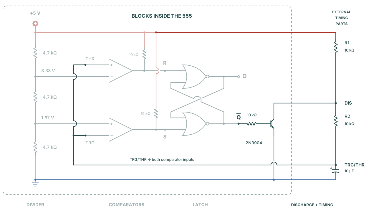
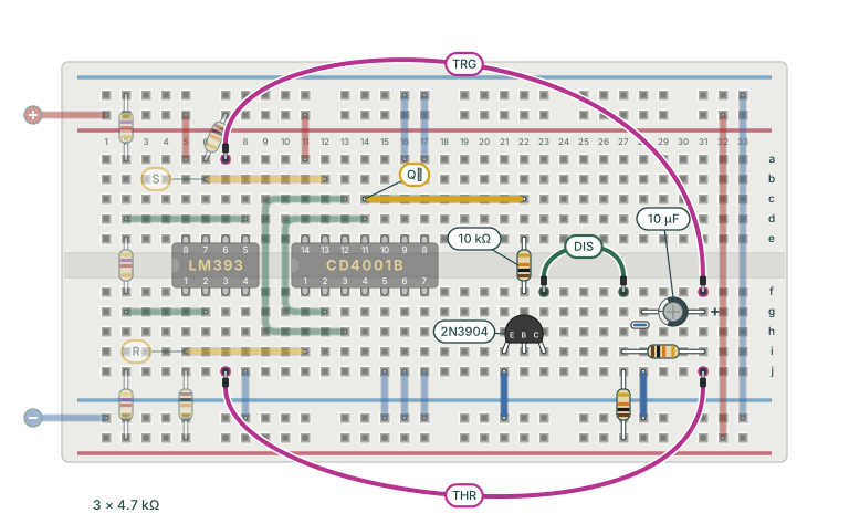
Stage 4 schematic: a dashed boundary separates the blocks inside a 555 from external timing resistors R1 and R2 and the capacitor. The previous divider, LM393 comparators and CD4001B latch stay in place, muted. Q̅ drives a 2N3904 base through 10 kilohms. Plus 5 volts feeds R1, DIS, R2 and TRG/THR in order. A 10 microfarad capacitor connects TRG/THR to the common ground. The collector connects to DIS and the emitter to ground. A label on the return wire reads: TRG/THR to both comparator inputs. Semicircular bridges mark crossings without connections.
Figure 2-9: The dashed boundary encloses the blocks we rebuild from inside a 555, including the discharge transistor. R1, R2 and the capacitor are external timing parts. When Q̅ is low, the transistor is off and the capacitor charges through R1 and R2. When Q̅ is high, the transistor is on and the capacitor discharges through R2 and the transistor. Pale components are already on the board. Click to enlarge.
  1. Connect the timing parts. Disable power supply output 1. Fit R1 (10 kΩ) from the bottom red rail into 27j. Fit R2 (10 kΩ) along row i from 27i to 31i. Insert the 10 µF capacitor with its positive lead at 31g and its negative lead at 28g. Connect a blue jumper from 28j to the bottom blue rail. Column 27 (holes f–j) is now DIS, and column 31 (holes f–j) is TRG/THR.
  2. Connect TRG/THR to both comparator inputs. Run the TRG jumper lead from 31f to 7a (LM393 pin 6). Run the THR jumper lead from 31j to 7j (LM393 pin 3).
  3. Check the transistor pinout. Identify the emitter, base and collector from the datasheet for your 2N3904. The onsemi TO-92 part in the component references at the end of this page has emitter, base and collector from left to right. Hold it with the flat face towards you and the leads pointing down. Other parts or packages may differ.
  4. Wire the discharge transistor. Insert the 2N3904 as Figure 2-10 shows: emitter at 21i, base at 22i, collector at 23i. Each lead then has its own numbered column. Connect a blue jumper from 21j to the bottom blue rail. Run a yellow wire from 14c (Q̅) to 22c. Fit a 10 kΩ resistor across the centre gap from 22e to 22f. Run the DIS jumper lead from 23f to 27f. Leave the LED disconnected until the first oscilloscope check.
Breadboard timing loop added to the muted divider, LM393 and CD4001B. The timing parts sit at the far right beside the rail links, on the lower half. R1 rises from the bottom red rail into column 27. R2 runs along row i from column 27 to 31. The 10 microfarad capacitor lies along row g with its positive lead at 31g and its negative lead at 28g, grounded by a short wire. A yellow wire along row c carries Q̅ from 14c to 22c, and a 10 kilohm resistor bridges the centre gap from 22e to 22f. The discharge transistor has emitter, base and collector at 21i, 22i and 23i, and the emitter is grounded. A green jumper lead tagged DIS arches from the collector column at 23f to DIS at 27f. Two magenta jumper leads leave TRG/THR at 31f and 31j. The one tagged TRG arches over the top of the board to LM393 pin 6. The one tagged THR arches under the board to LM393 pin 3.
Figure 2-10: The timing loop added to the same breadboard. Pale parts stay in place. The tagged jumper leads are the three 555 connections. DIS runs from the collector to the timing resistors. TRG and THR run from the capacitor to the comparators. Keep the LED disconnected. Click to enlarge.

Watch the timing loop run

The timing loop is now complete. The capacitor feeds the comparators, the comparators control the latch, and the latch controls the discharge transistor. Until now, you checked individual blocks. This test shows whether they work together and repeat the charge and discharge cycle on their own.

Watch two signals together on the oscilloscope: the capacitor voltage at TRG/THR and the latch output Q. Side by side, they show whether Q changes state at the capacitor's upper and lower limits. Then measure those limits and the time for one cycle, as you did with the reference 555.

Expect TRG/THR to rise from about 1.67 V to 3.33 V, then fall to 1.67 V again. Q should be high during the rise and low during the fall. The capacitor charges through R1 and R2 and discharges through R2 alone, so the rise should last about twice as long as the fall.
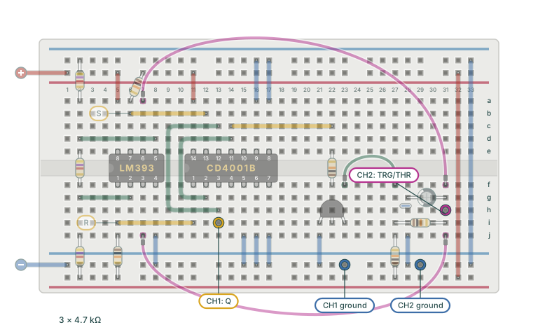
The finished Experiment 2 breadboard, muted, with the oscilloscope hookup in colour. The oscilloscope channel 1 probe tip marked in yellow is on Q at 13i, CD4001B pin 3. The oscilloscope channel 2 probe tip marked in magenta is on TRG/THR at 31h, the capacitor column. Two ground clips marked in blue sit on the bottom blue rail at 23 and 29.
Figure 2-11: Oscilloscope hookup. The oscilloscope channel 1 probe tip sits on Q at 13i, and the oscilloscope channel 2 probe tip on TRG/THR at 31h. Both ground clips sit on the bottom blue rail. Click to enlarge.
  1. Connect both probes with the supply disabled. Connect one probe to the oscilloscope input marked CH1. Connect the other probe to the input marked CH2. Put the oscilloscope channel 1 probe tip on Q at 13i (CD4001B pin 3). Put the oscilloscope channel 2 probe tip on TRG/THR at 31h. Connect both ground clips to the bottom blue rail. These ground connections match Experiment 1's oscilloscope hookup.
  2. Set the oscilloscope. Set the switch on each probe to 10X. Set the Probe value for oscilloscope channel 1 and oscilloscope channel 2 to 10X. Enable both channels with DC coupling and 1 V/div. Set the timebase to 50 ms/div. Move each channel's ground marker near the bottom of the screen, so 0–5 V fits. Select an edge trigger on oscilloscope channel 1, rising slope, Auto mode, level about 1.5 V.
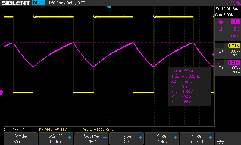
  3. Enable the supply and check. Enable power supply output 1. Expect a repeating capacitor waveform on oscilloscope channel 2 and a square wave on oscilloscope channel 1. A cycle should take about 0.21 s.
  4. Measure the capacitor. Press Cursors and select Manual. Set the oscilloscope cursor Source to CH2. Place Y1 at the lower turnaround and Y2 at the upper turnaround. Place X1 and X2 at consecutive peaks. Read the period ΔX and the frequency 1/ΔX. Record these readings and the measured supply voltage.
  5. Measure Q's high level. Set the oscilloscope cursor Source to CH1. Place Y2 on Q's high level. Record that voltage. Section 5 compares it with the level under an LED load.
Oscilloscope screen. The magenta oscilloscope channel 2 trace is the capacitor voltage at TRG/THR. It is a sawtooth that rises slowly and falls faster, between cursor lines Y1 at 1.66 volts and Y2 at 3.34 volts. The yellow oscilloscope channel 1 trace is Q, a square wave that is high during each rise and low during each fall. Cursors X1 and X2 span one cycle: 199 milliseconds, 5.025 hertz. Both channels are 1 volt per division, timebase 50 milliseconds per division.
Figure 2-12: My capture of the timing loop. Oscilloscope channel 2 (magenta) shows TRG/THR, which moves between 1.66 V and 3.34 V. Oscilloscope channel 1 (yellow) shows Q, high while the capacitor charges. The cursors span one cycle of 199 ms, about 5 Hz. I triggered on oscilloscope channel 2 for this capture. Click to enlarge.

If the capacitor stays low, check that the discharge base resistor goes to pin 11 (Q̅). A base wired to pin 3 (Q) holds the transistor on during the charge, and the capacitor stays at ground. If the capacitor stays high, check the discharge transistor's pinout and the threshold comparator wiring. If neither signal changes, check the chip power, the two pull-ups and the latch feedback. Disable power supply output 1 before each correction. For an unexpected voltage, check the cursor source and probe settings before you change the circuit.

How one cycle runs

Figure 2-12 shows the loop running. Here is one cycle on your board, step by step.

  1. At power-up the 10 µF capacitor sits at 0 V. TRG (LM393 pin 6) is below the 1.67 V on pin 5. The LM393 output transistor on pin 7 is then off, and its 10 kΩ pull-up raises S to about 5 V.
  2. S high drives the output of gate D, Q̅ at CD4001B pin 11, low. Gate A now has two low inputs, so Q at pin 3 goes high. With Q̅ low, the discharge 2N3904 gets no base current and stays off.
  3. The capacitor charges from +5 V through R1 and R2, 20 kΩ in total. Once it passes 1.67 V, S falls low and the latch keeps Q high.
  4. At 3.33 V, THR (pin 3) rises above the upper reference on pin 2. The LM393 output transistor on pin 1 is then off, and its pull-up raises R. Gate A drives Q low. Gate D, now with two low inputs, drives Q̅ high.
  5. Q̅ sends about 0.43 mA, (5 − 0.7) V / 10 kΩ, into the transistor's base. The transistor pulls DIS to near ground, and the capacitor discharges through R2 alone, 10 kΩ. Below 3.33 V, R falls low and the latch keeps Q̅ high.
  6. At 1.67 V, S goes high again and the cycle repeats from step 2. The charge takes about 0.693 × 20 kΩ × 10 µF ≈ 139 ms and the discharge about 69 ms, 208 ms in all. My board measured 199 ms with the cursors in Figure 2-12.

5. Add the output driver

The loop runs on its own: Figure 2-12 shows one cycle every 199 ms, with Q high through each charge. The other branch after the latch supplies current to a load. Before you add its transistor, measure what happens when the latch drives the LED directly.

Try the LED on the latch output

Add a load to Q and measure its effect on Q's high level. Leave both probes where they were: oscilloscope channel 1 on Q, oscilloscope channel 2 on TRG/THR. This short test checks how much current the CD4001B can supply. The oscilloscope shows the result.
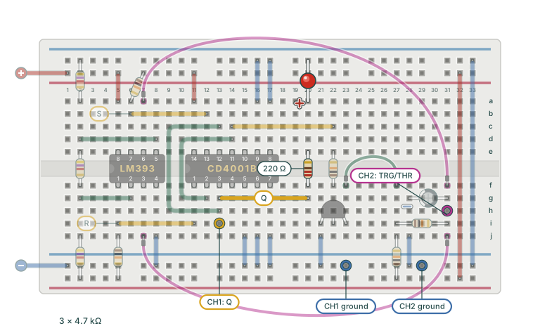
  1. Add the LED with the supply disabled. Disable power supply output 1. Leave both probes attached. Run a yellow wire from 13g (Q) to 20g. Fit the 220 Ω resistor across the centre gap from 20f to 20e. Insert the LED with its anode at 20a and its cathode in the top blue rail. The cathode is usually the shorter lead, on the side with a flat edge on the body.
  2. Measure Q on the oscilloscope. Enable power supply output 1. Oscilloscope channel 1 should still show a square wave. Set the oscilloscope cursor Source to CH1. Place Y1 on the low level and Y2 on the high level. Read both voltages. Compare the high level with the value you recorded in the timing loop check. Your LED may be dim, and the high level may fall substantially. If the timer stops, disable power supply output 1 and remove the LED branch. Check that the loop runs again, then continue to the driver below.
The finished timing loop, muted, with the direct LED test in colour. A yellow wire from Q at 13g, CD4001B pin 3, runs along row g to 20g. A 220 ohm resistor crosses the centre gap from 20f to 20e, and the LED runs from its anode at 20a to the top blue rail. The oscilloscope probes from Figure 2-11 stay in place. The oscilloscope channel 1 probe is on Q at 13i, and the oscilloscope channel 2 probe is on TRG/THR at 31h. Both ground clips sit on the bottom blue rail.
Figure 2-13: The LED connected directly to Q: Q, 220 Ω, LED, ground. The probes stay where Figure 2-11 put them. Pale parts stay in place. Click to enlarge.
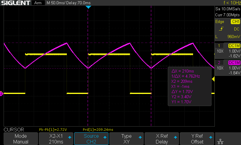
Oscilloscope capture with oscilloscope channel 2 capacitor cursors at 1.70 V and 3.40 V and a loaded oscilloscope channel 1 output high near 2.6 V.
Figure 2-14: My direct LED test. The magenta trace (oscilloscope channel 2) shows the voltage at TRG/THR, with cursor readings of 1.70 V and 3.40 V. The yellow trace (oscilloscope channel 1) shows Q, whose high level has fallen to about 2.6 V. The automatic period reading is 209.24 ms, about 4.78 Hz. The manually placed X cursors give a slightly different 210 ms.

These are my recorded values. Treat them as a guide, because the LED type, component tolerances and measurement setup all shift the readings.

In Figure 2-14, Q's high level fell to about 2.6 V. The CD4001B can supply some output current. This LED and its 220 Ω ask for more current than the gate can supply while its output stays near 5 V. A loaded latch output may also stop being a reliable high for the other NOR gate. Other logic families and lighter LED loads can behave differently.

Give the LED its own transistor

Q's high level fell with the LED connected, so the LED gets its own transistor. With a second NPN transistor, the supply provides the LED current and Q supplies only a small base current. This transistor is a grounded-emitter switch, like the discharge transistor. Its base connects to Q through 10 kΩ, and its emitter connects to ground. The LED and its 220 Ω connect from +5 V to its collector. When Q is high, the transistor is on, pulls the collector low and lights the LED.

This output stage suits our LED load. It shows why a separate driver between the latch and the load helps. It does not copy the complete output stage of the NE555.
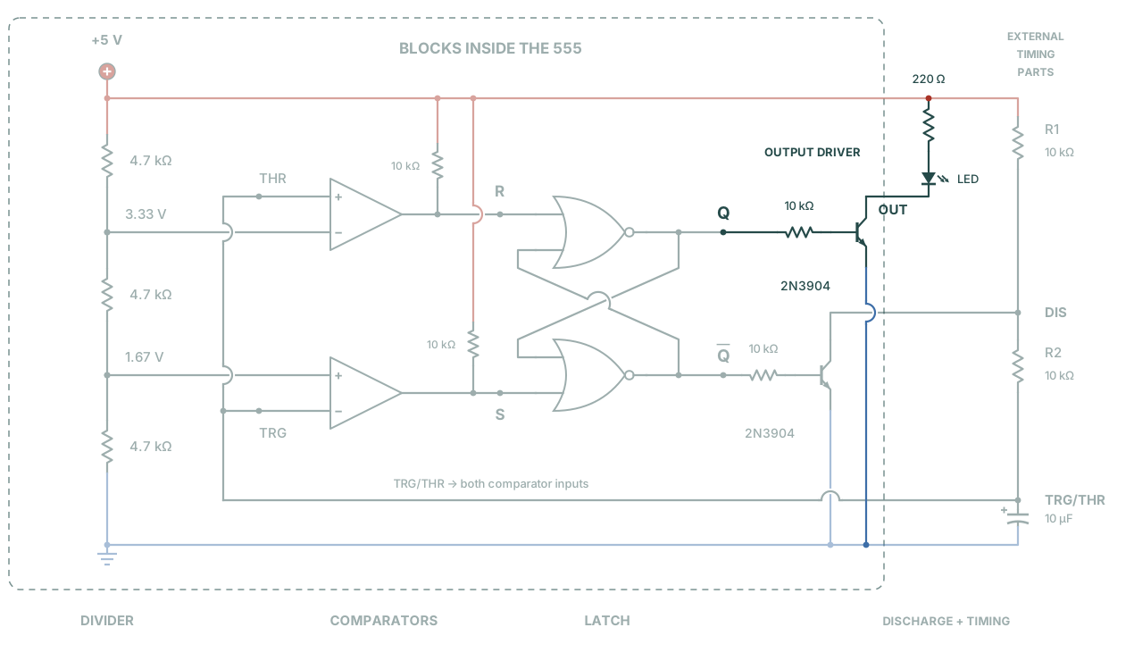
Stage 5 schematic: the divider, comparators, latch and timing loop from Figure 2-9 stay in place, muted, and the output driver appears in colour. Inside the dashed boundary, above the discharge transistor, Q drives a second 2N3904 base through 10 kilohms. Its emitter drops straight to the common ground and hops over the DIS wire and the TRG/THR return. The collector is the node OUT. It leaves the boundary and rises through the LED and 220 ohms to the +5 volt rail, in the gap before the timing parts.
Figure 2-15: The output driver added to the schematic, a grounded-emitter switch. When Q is high, the transistor is on and pulls its collector, OUT, low, so the LED lights. The LED and its 220 Ω are the external load, connected from +5 V to the collector. Oscilloscope channel 1 stays at Q, before the base resistor. Pale parts are already on the board. Click to enlarge.
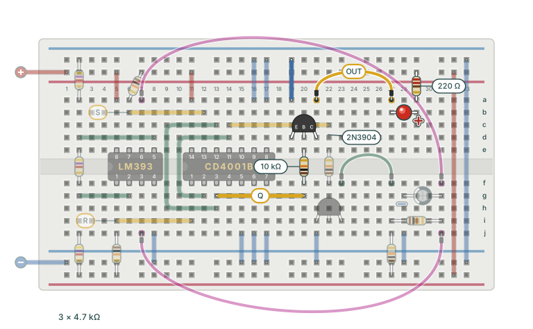
  1. Remove the direct LED branch with the supply disabled. Disable power supply output 1. Remove the 220 Ω resistor and the LED. Keep the yellow wire from 13g to 20g: it now carries Q to the driver's base resistor. Keep the discharge transistor and its base resistor in place, because they still control the discharge.
  2. Add the second 2N3904. Insert it with its emitter at 19d, base at 20d and collector at 21d. Connect a blue jumper from 19a to the top blue rail. Fit the remaining 10 kΩ resistor across the centre gap from 20f to 20e. The collector is the output, OUT.
  3. Reconnect the LED load. Run the OUT jumper lead from 21a to 27a. Insert the LED with its cathode at 27b and its anode at 29b. Fit the 220 Ω resistor from the top red rail into 29a. Check the LED polarity and the transistor pinout before you enable power supply output 1.
  4. Compare the gate voltage. Keep the oscilloscope channel 1 probe on Q at 13i and the oscilloscope channel 2 probe on TRG/THR. Enable power supply output 1. Set the oscilloscope cursor Source to CH1. Measure the low and high levels again. Expect the high level to recover towards the supply. Expect the LED to light while the capacitor voltage rises. The gate still supplies a small base current, so it carries a light load.
  5. Look at OUT. Move the oscilloscope channel 1 probe tip to the collector, on the OUT jumper lead. OUT is the opposite of Q: low while the capacitor charges and the LED lights, high while the capacitor discharges. Return the probe tip to Q at 13i afterwards.
The finished timing loop, muted, with the output driver in colour. As in the direct LED test, a yellow wire from Q at 13g, CD4001B pin 3, runs along row g to 20g. A 10 kilohm base resistor crosses the centre gap from 20f to 20e. A second 2N3904 sits at 19d, 20d and 21d with emitter, base and collector from left to right. A blue wire grounds the emitter from 19a to the top blue rail. The collector is the output. A yellow jumper lead tagged OUT arches from 21a to 27a. There the LED runs along row b from its cathode at 27b to its anode at 29b. A 220 ohm resistor drops from the top red rail into 29a.
Figure 2-16: The output driver added to the same breadboard. Pale parts stay in place, and the direct LED branch is gone. The tagged jumper lead is the fourth 555 connection, OUT, from the collector to the LED and its 220 Ω at the far right. Click to enlarge.

OUT is the opposite of Q because a grounded-emitter stage inverts: a high at the base pulls the collector low. OUT is therefore low while the capacitor charges and high while it discharges. That is upside down relative to pin 3 of an NE555. In Stage Four, the master schematic of Experiment 14 moves this transistor's base to Q̅. The inversion then turns Q̅ back into Q at OUT.

When the transistor is on, it holds OUT near ground. When it is off, the LED and 220 Ω give a weak pull-up path. The measured high level depends on the LED’s current–voltage characteristic and on the load, including the oscilloscope probe. This output drives the LED, and its high level has no specified logic value.
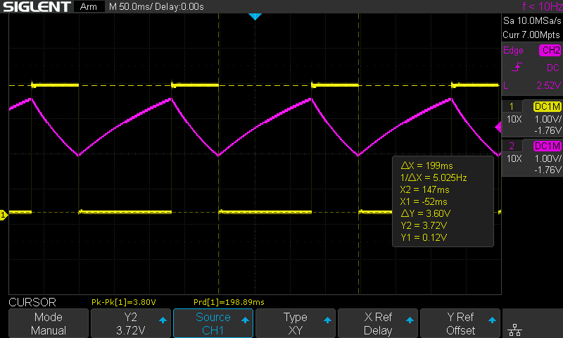
Oscilloscope capture with oscilloscope channel 1 on OUT, the driver's collector. OUT is a square wave, the inverse of the capacitor: high during the fast discharge and low during the slow charge. Cursors on the two levels read Y1 0.12 V and Y2 3.72 V, a 3.60 V swing. The magenta oscilloscope channel 2 trace is the capacitor sawtooth at TRG/THR. X cursors span one cycle, 199 ms, 5.025 Hz.
Figure 2-17: My capture with oscilloscope channel 1 on OUT, the collector. It is the inverse of Q: a short high through the discharge and a long low through the charge. Oscilloscope channel 2 shows the capacitor. The cursors read a low of 0.12 V, where the transistor holds OUT, and a high of 3.72 V. With the transistor off, the oscilloscope probe and leakage draw a small current through the LED and 220 Ω. The LED’s forward voltage at that small current probably accounts for much of the gap below +5 V. This level depends on the measurement load. The NE555 has a different, actively driven output stage. The X cursors span one cycle, 199 ms, 5.025 Hz.

Compare the timers

With the driver fitted, Q's high level recovered, and Figure 2-17 shows the same 199 ms cycle as Figure 2-12. The table compares that rate with the formula and the reference chip.

Formula or buildFrequency
Formula, with 10 kΩ, 10 kΩ and 10 µF4.81 Hz
My NE555 reference (Experiment 1)About 4.98 Hz
My IC timer, with the output driverAbout 5.02 Hz

With the driver fitted, the IC timer runs about 4.5% above the formula and within 1% of the reference chip. The same nominal R and C values and the same one-third and two-thirds thresholds explain the similar timing. The match is close but inexact. Component tolerances, the actual switching levels and the discharge transistor's on-state voltage can all contribute to the difference.

The direct LED test in Figure 2-14 measured 4.78 Hz while Q carried a heavy load. The driver measurement is closer to the reference. These captures alone do not show how much of the frequency difference came from the load and how much came from other changes between measurements.

Compare your two boards with the same oscilloscope settings. Record the IC timer's period, frequency and capacitor limits with the driver fitted. Record Q's low and high levels too. The check is that the loop oscillates near the rate the formula gives. The exact figure depends on your parts and their switching levels.

You built a 555 from off-the-shelf parts. A three-resistor divider sets the two references. The LM393's two comparators watch the capacitor against them. The CD4001B provides the latch's two NOR gates. One transistor discharges the capacitor, and a second drives the LED. Together they charge and discharge the capacitor and blink the LED near 5 Hz, the same loop the reference chip ran in Experiment 1.

The five blocks of Figure 2-1 now run on your bench. Stage Three rebuilds each of them from individual transistors, starting in Experiment 3.

Quick check

1. Why does this timer need a latch?

Between the references, both comparator outputs are low. Feedback in the latch keeps the last state until set or reset requests a change.

2. Why does each LM393 output need a pull-up resistor?

The pull-up supplies a defined high when the open-collector output transistor is off. When that transistor conducts, it pulls the output low.

3. What changes when you add the output driver?

The two transistors have separate jobs. One switches the LED current. The other controls the capacitor's discharge path. Both still need their base resistors.

Before moving on

Keep this board assembled beside the NE555 reference. Save an oscilloscope capture. Record the probe points, the supply voltage and your measurements. Experiment 12 compares these boards with the transistor timer.

Experiment 3 starts with one transistor and develops it into a comparator, step by step. If you get stuck, you can ask me at @dnixty. A board photo, your probe points and your measurements help me answer.

Component references: LM393 datasheet, CD4001B datasheet, and onsemi 2N3904 datasheet.

Contents All experiments