Full Stack Electronics · The 555, from Transistors
Why this course exists, how it works, and what you'll build.
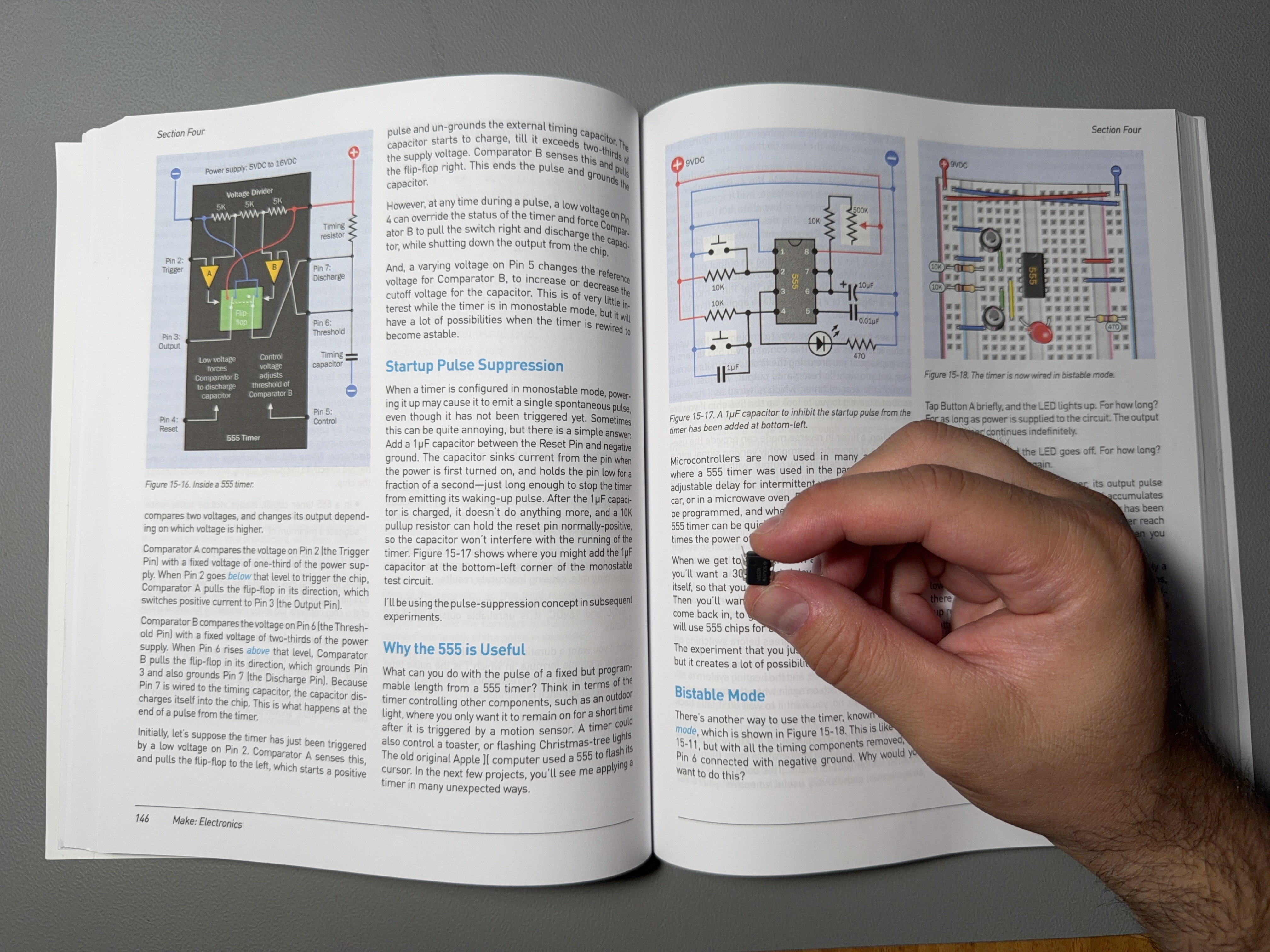
I met the 555 in Charles Platt's Make: Electronics. The timer blinked on my breadboard, and I could not have told you what was happening inside the chip. Two comparators and a flip-flop: I could name the blocks, but I couldn't explain them. I wanted to build its insides and watch them work.
I knew logic gates from From Nand to Tetris. Analogue electronics was less familiar, and I wanted time with it before I took my own projects further into digital hardware. Rebuilding the 555 from individual transistors and resistors gave me a reason to learn both the circuits and the tools. Taking that build to a PCB would make me learn schematic capture, simulation, layout and surface-mount soldering too.
I found guides to using the chip and schematics that presented twenty-odd transistors all at once. I couldn't find the explanation I needed. I wanted to know what each transistor contributes, how to measure it, and how to take that knowledge to a board of my own. So, while building an electronics lab, I built each stage and documented my builds. Those notes became this course.
You should be comfortable with a breadboard and know Ohm's law, roughly the level of someone who has completed Make: Electronics. If you're coming from software, that is the starting point to aim for. The course assumes no calculus, KiCad or surface-mount experience. The course introduces the transistor circuits, instrument techniques and board-design tools as you need them.
Twenty-one experiments build the same timer four ways. Each stage ends with a working circuit. Keep the earlier builds intact, so that you can compare each new build with them as you replace more of the chip with your own wiring.
Build a repeating LED blinker around a shop-bought NE555. Measure its timing and the voltage across its capacitor. These measurements give you a reference for the rebuilds that follow.
Rebuild the timer with comparator and logic ICs. The connections hidden inside the NE555 are now wires you can trace and signals you can probe. You check each block on its own, then run them together, before you build them from individual transistors.
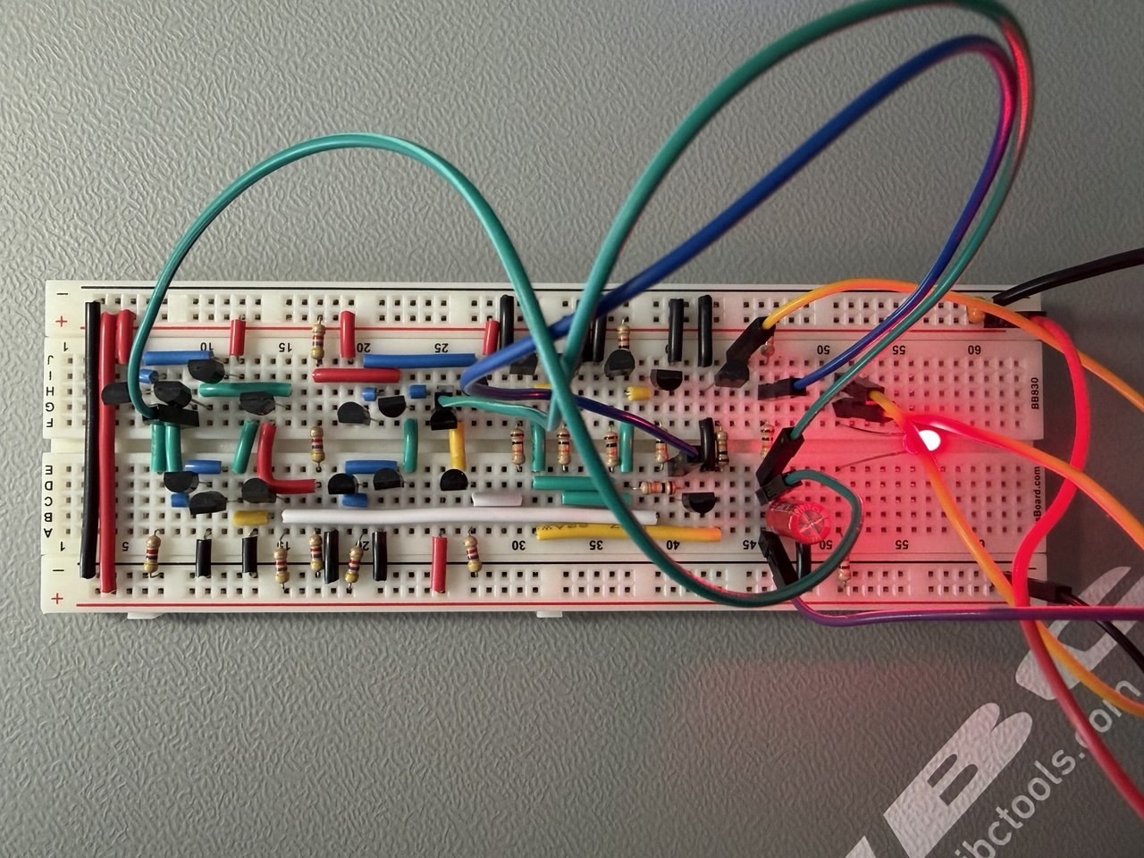
A single transistor makes a crude comparator. The next experiments fix its limitations one at a time. You measure a limitation, build an improvement, and check what changed. Step by step, you build the two comparators, then the logic gates and memory that control the timer. Join the blocks, add the reset circuit, and you have a twenty-three-transistor 555 to compare with the chip.
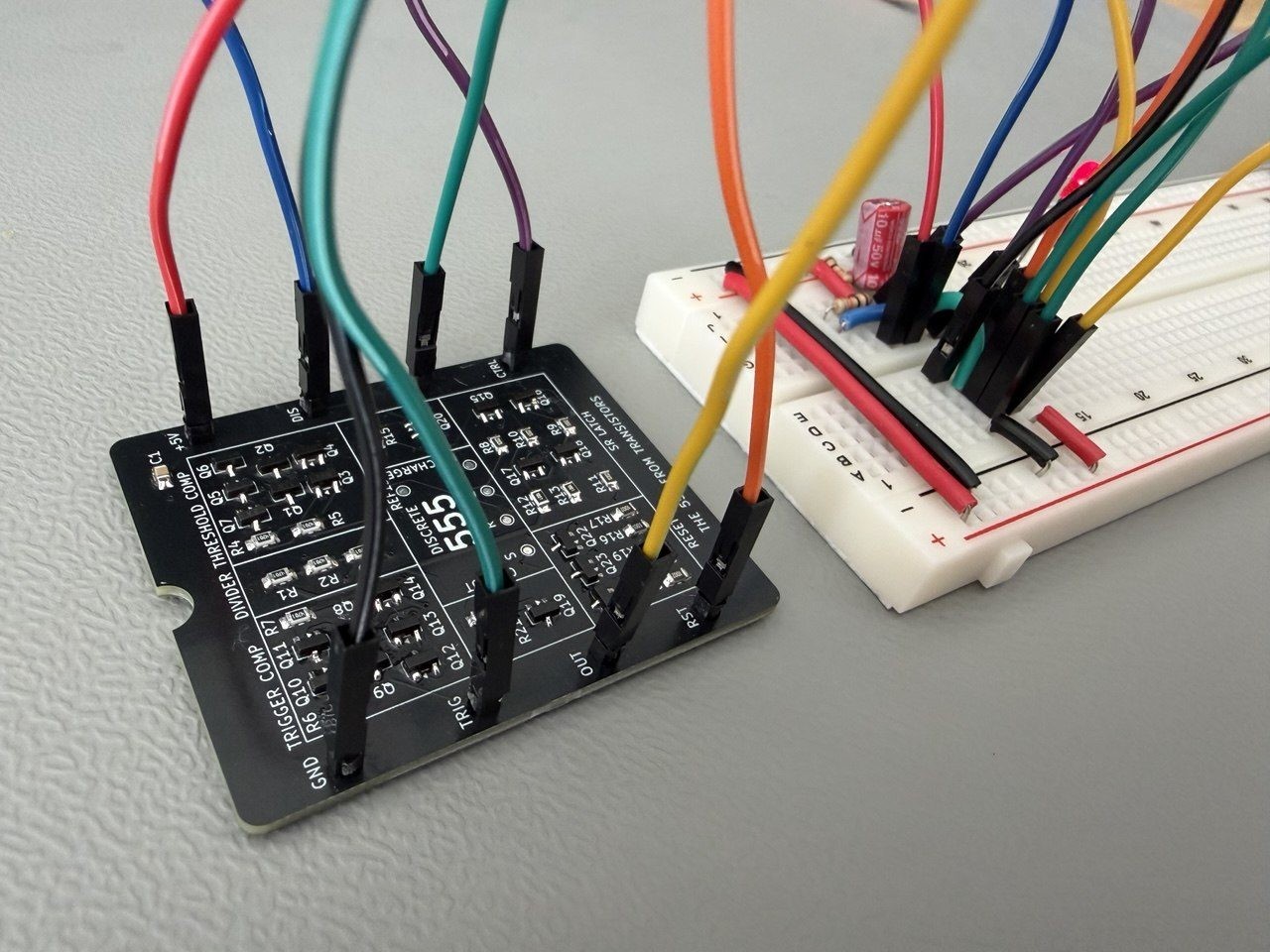
Draw the schematic in KiCad and check its behaviour in SPICE. Choose surface-mount packages, place the components and route the connections. Use your breadboard measurements to guide the layout. Check the design, have the board made, then solder and inspect it. At first power-up, use the measurements from your earlier builds to check whether it behaves as expected.
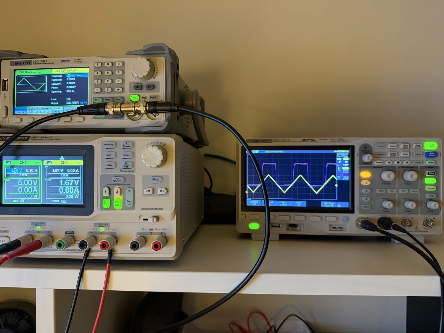
Each experiment guides you through the build and the measurements. It explains what to connect, how to set your instruments and what to look for. Before each measurement, it states the value to expect and the reason for it. You compare your reading with that value, and the checks help you find common mistakes. The sequence is build, measure, explain.
The oscilloscope captures and board photographs come from my builds of these circuits. Instrument instructions give the purpose of each operation and the keystrokes for the reference bench. If your instruments are different, use that purpose to find the equivalent controls. The glossary defines the technical terms.
Keep notes of the expected values, your measurements and your changes. When a build doesn't work, those notes help you trace what happened. They also make it easier to ask for help: explain what you built, what you expected, and what you measured.
If you get stuck or something in the course is confusing, you can ask me at @dnixty. You can also try Electrical Engineering Stack Exchange for a specific question, the EEVblog forum for a build thread, or r/AskElectronics for help with a breadboard photo.
Plan for roughly twenty-one evenings of experiments, with extra time for unfamiliar tools, debugging and rework. Board fabrication and delivery add waiting time between the design and assembly stages.
Budget for components, breadboards and wiring, PCB fabrication and delivery, and soldering consumables. Equipment is a separate cost and depends on what you already own or can borrow.
For the measurement stages: an oscilloscope, a function generator, a power supply with two independently adjustable outputs, a multimeter and a hair dryer or heat gun, plus breadboards, wiring and components. Stage Four adds soldering tools, consumables and magnification.
The Bench lists the instruments and their minimum capabilities. The Parts carries the shopping list. Read both before Experiment 1.