Full Stack Electronics · The 555, from Transistors
The equipment you'll use, what it does, and when you'll need it.
The instruments let you see what your circuit is doing: where the voltages change, when a transistor switches, and how the timer produces a pulse. You don't need to know how to use them yet. Each experiment guides you through the connections, settings and measurements.
Compare what you already own or can borrow with the features below. The named models are the ones I use, and the course gives button-by-button instructions for them. Other models can work too: each instruction explains what you're trying to do, so you can find the equivalent control on yours.
For Stages One to Three: measurement instruments, cables, breadboards, basic wiring tools and a hair dryer or heat gun.
For Stage Four: a computer for circuit design and simulation, then soldering tools and magnification for assembly. You can leave those preparations until you reach that stage.
The components are listed separately in The Parts. The checklist at the end of this page helps you track the equipment.
| Instrument | Reference bench | Features and use |
|---|---|---|
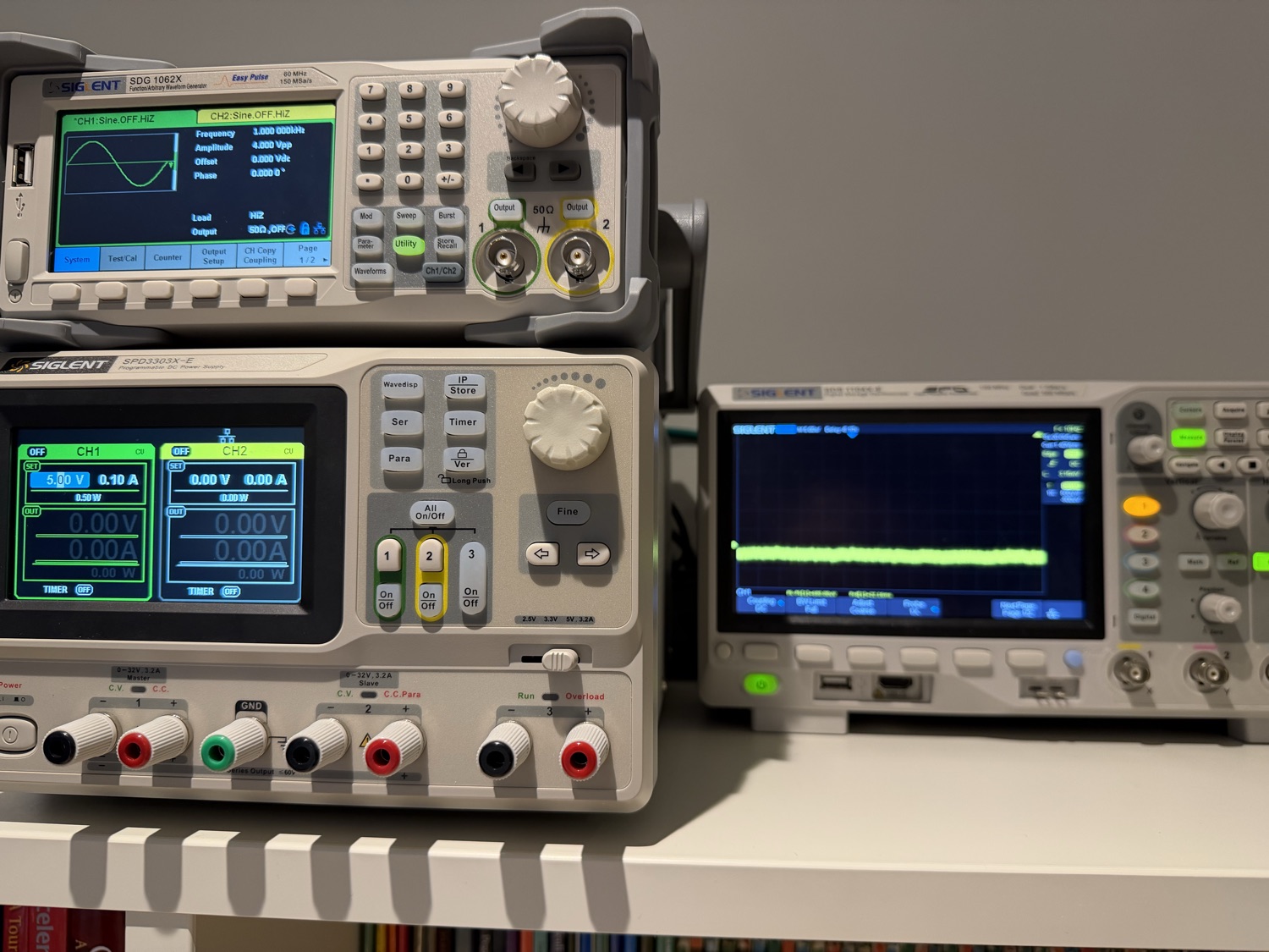
| Bench power supply | Siglent SPD3303X-E | Required: two independently adjustable voltage outputs and adjustable current limiting. One output powers the circuit. The other supplies a voltage for comparison. The current limit helps reduce damage if you make a wiring mistake. The experiments give you the settings. |
| Oscilloscope | Siglent SDS1104X-E (4 ch) | Required: at least two channels, X-Y mode, measurement cursors and persistence. These let you compare signals, plot one voltage against another, measure switching points and keep previous traces visible. Useful extras: four channels show more signals at once, and colour grading makes repeated traces easier to distinguish. |
| Function generator | Siglent SDG1062X | Required: a triangle wave at around 100 Hz, adjustable upper and lower voltages (or amplitude and DC offset), and a high-impedance (HiZ) load setting. It supplies a slowly rising and falling voltage so you can find where a circuit switches. On a 50 Ω load setting, a generator delivers about twice the displayed voltage into a breadboard. The HiZ setting makes the display match the output. |
| Multimeter | Brymen BM235 | Required: DC voltage measurement with 0.01 V resolution around 5 V, a milliamp current range, resistance measurement and a continuity beep. You use it to check wiring and measure steady voltages, currents and resistor values. |
| Cabling | – | One BNC cable, a BNC T-piece, a BNC-to-mini-hook lead and the oscilloscope probes. These connect the function generator to both the breadboard and the oscilloscope. You also need leads from the power supply to the breadboard, and multimeter leads. Check what comes with your instruments. |
| Heat source | – | A hair dryer, or a heat gun on its lowest setting, to warm a transistor in Experiments 3 and 4. |
You solder the surface-mount components onto your PCB and inspect the connections before you apply power. The course guides you through the assembly, and you can assemble the board with a soldering iron. The resistors and transistors are small, so good lighting, magnification and a stable work surface matter.
| Tool | Reference bench | Features and use |
|---|---|---|
| Soldering station | JBC CD-2BQF | Temperature control and a small chisel or fine conical tip suitable for the pads. It should hold its temperature while you solder pads that connect to larger areas of copper. |
| Magnification | AmScope SM-3 stereo microscope | Enough magnification to read component markings and inspect individual solder joints. A stereo microscope gives room to work beneath it. You can also use a 10× loupe for inspection. A USB microscope is another option if its working distance and image delay let you work comfortably. |
| Fume extraction | Hakko FA-400 fan with a carbon filter (its limits are in the next column) | Capture solder fumes close to the joint and keep your face out of the plume. Choose extraction intended for soldering fumes, with suitable filtration or exhaust outdoors. Do not assume that a basic fan with a thin carbon filter gives adequate control. See HSE's solder-fume guidance. |
You use KiCad to draw the schematic and design the PCB layout, and ngspice to simulate the circuit. The instructions use KiCad 10. Before you install it, check the system requirements for your computer.
You don't need to learn KiCad in advance. Experiment 15 introduces schematic capture. Experiment 16 guides you through the simulation, including the terminal commands. Have KiCad, its standard libraries and ngspice ready when you reach those experiments.
Tick each item when you have it. This browser saves the ticks, and they are still here when you return.