Full Stack Electronics · Stage Three · Experiment 5
Build a current source from two transistors, and give the pair a tail that holds its current.
In Experiment 4 you tied the pair's two inputs together and swept them from 1 V to 2 V, and the output moved by about 2.4 V. The meter traced the cause to the tail. The current through the 1 kΩ tail resistor rose from 0.39 mA to 1.36 mA as the emitters rose with the inputs. Inside the 555 one comparator works with its inputs near 1.67 V and the other near 3.33 V. With a resistor tail the second comparator would draw about 2.7 mA. Half of that through a 4.7 kΩ collector resistor needs 6.3 V, more than the supply.
The tail needs to pass the same current whatever voltage sits across it. This experiment builds that circuit from two more transistors and tests it alone with the meter. Then it fits the circuit under the pair and repeats the common-mode sweep and the transfer curve.
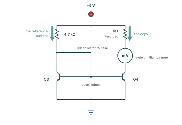
The circuit is called a current mirror. Two transistors share one base connection, and a resistor from the supply sets a known current through the first. The second transistor draws a copy of that current through whatever load connects to its collector. The copy stays the same when the load changes, and a tail needs exactly this behaviour. Integrated circuits commonly give a differential pair a tail made this way. Experiment 6 uses a second mirror in a different place, as the pair's load.
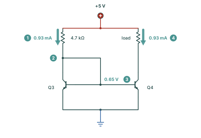
Figure 5-1 shows the circuit alone. Q3 and Q4 are two more 2N3904s, with their emitters on the ground rail and their bases joined. A wire joins Q3's collector to its own base. Q3 then has two working terminals and behaves as a diode, an arrangement called diode-connected. A 4.7 kΩ resistor from +5 V feeds Q3's collector, and the current through this resistor is the reference current. Q4's collector is the output, and for the test it connects through the meter to a 1 kΩ load from +5 V.
Start from the board of Figure 4-2, as Experiment 4 left it. The pair is in place, with the 1 kΩ tail from 12j to the ground rail. The generator's red lead is in 10c, and the positive lead of power supply output 2 is in 13c. The oscilloscope channel 2 probe is on 14i. This experiment adds to that build. Figure 5-2 draws the parts already there faded and the new parts in colour, as the rest of the course does.
The mirror goes to the left of the pair. Q4's collector at column 8 then sits next to Q1's emitter at column 9, so later a single short jumper makes the tail connection. For the test, a jumper brings Q4's collector into the upper block, where the load and the meter's leads have room. The pair stays on the board and takes no part in this test.
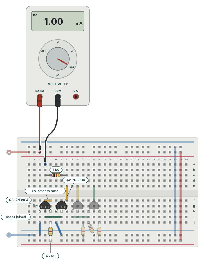
Steps 4 and 5 put the meter in series with the load. On its milliamp range the meter is close to a short circuit between its leads. Keep it in series with the load, as in Figure 5-2. Never connect it across the supply or across a resistor, because that can blow the meter's fuse. After a current reading, return the red lead to the voltage socket before any other measurement.
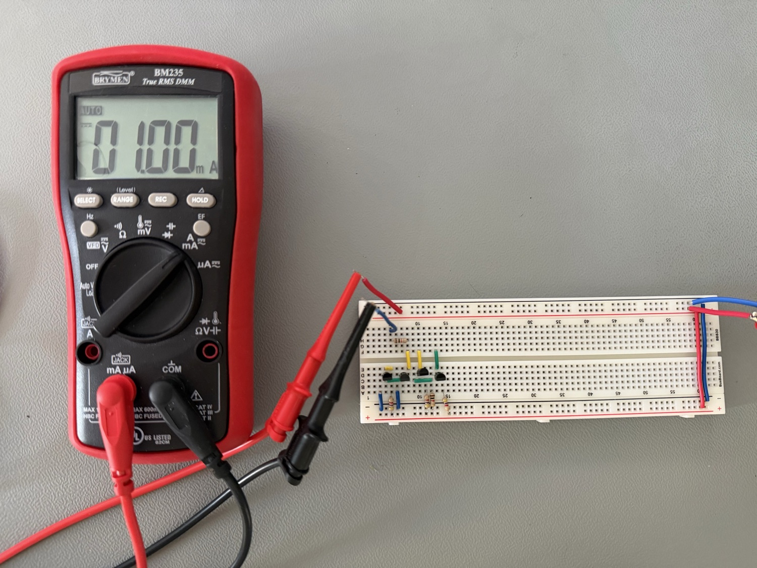
On my board the meter read 1.00 mA for the copy, as Figure 5-3 shows. The 4.7 kΩ sets the reference current that Q4 copies. Its ends sit at +5 V and at Q3's base-emitter voltage, about 0.65 V as in Experiment 4. So the resistor carries 4.35 V ÷ 4.7 kΩ, about 0.93 mA. The copy came out about 7 % above that. The theory box after the explanation below shows why a copy comes out a little off.
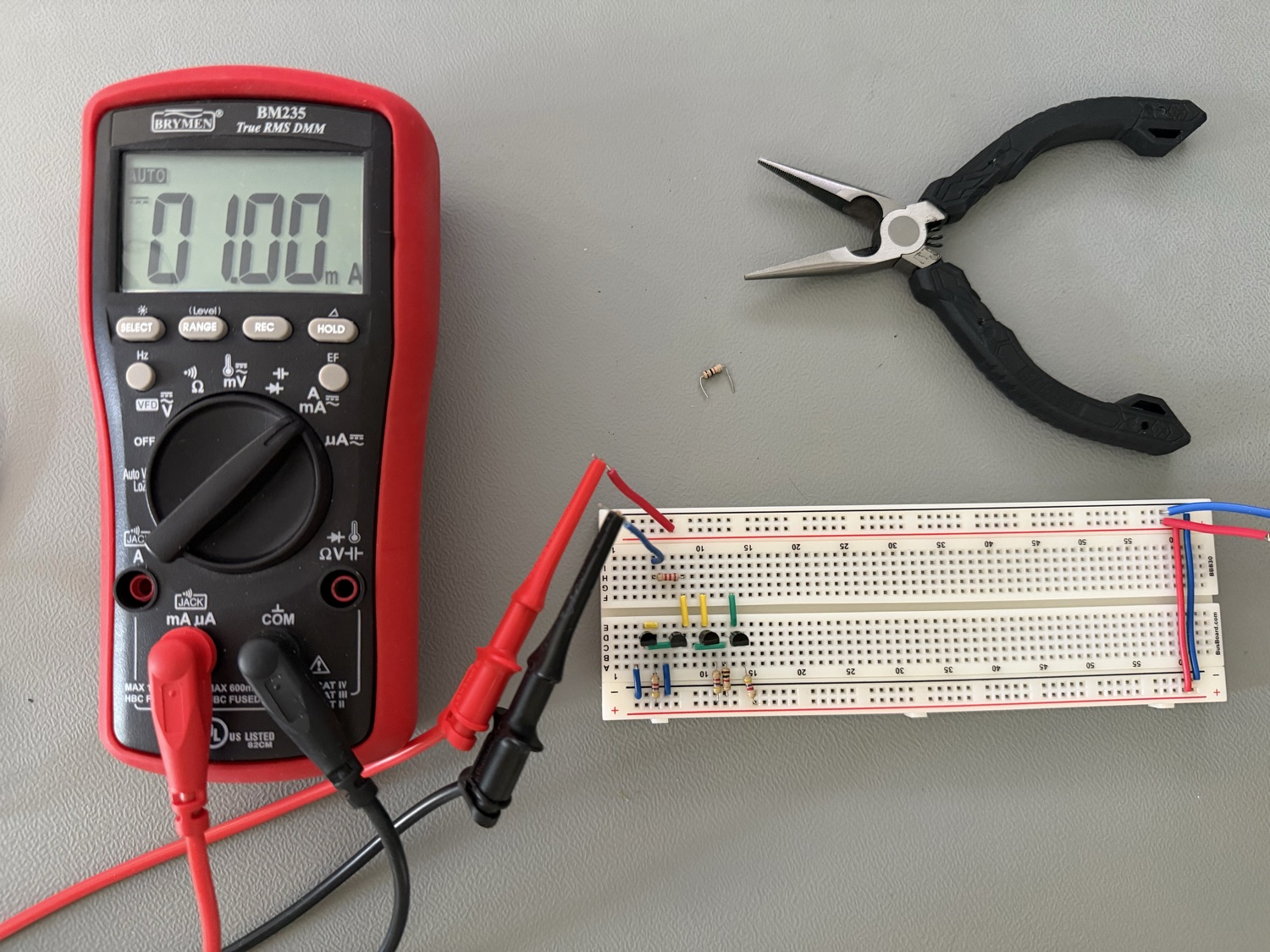
One reading gives the copy's value. A current source must keep that value when the load changes, so the next test changes the load. Switch off the 5 V supply. Replace the 1 kΩ with the 2.2 kΩ, and switch on again. With a fixed voltage across the load, the current would fall to less than half, because 2.2 kΩ is more than twice 1 kΩ. The meter read 1.00 mA again, the same to the last digit, as Figure 5-4 shows.
The voltage across the load works out at 1.00 V and then 2.20 V, and the current stayed the same. That is a current source: the circuit sets the current, and the voltage across the source settles where the load requires.
| Test load | Q4's current, measured | Voltage across the load, worked out |
|---|---|---|
| 1 kΩ | 1.00 mA | 1.00 V |
| 2.2 kΩ | 1.00 mA | 2.20 V |
This behaviour holds only up to a point. Q4 holds its current only while its collector stays a few tenths of a volt above its emitter. At 1.00 mA a load above about 4.7 kΩ would drop more than 4.7 V. That leaves Q4 less than 0.3 V, and Q4 saturates, as Q2 did in Experiment 4. Later in this experiment the differential pair replaces the load, and the same condition applies there. Q4 keeps its current while its collector stays a few tenths of a volt above ground.
The two readings in the table show the behaviour of a current source. A resistor passes the current that the voltage across it sets, and the current changes as soon as the voltage changes. A current source passes a set current and lets the voltage across itself settle where the rest of the circuit needs it. A source set to 1 mA passes 1 mA through a 1 kΩ, a 2.2 kΩ or a differential pair. It adjusts its own voltage to do it. A tail needs exactly this behaviour: one steady current while the voltage across the tail moves with the common-mode level.
The table showed Q4 holding 1.00 mA into both loads. The mirror does this because of one property of a transistor: the voltage between its base and its emitter sets the current into its collector. Experiment 4 found the emitters about 0.65 V below the bases with about a milliamp flowing. Its theory box gave the rule that every extra 60 mV multiplies the current by ten. So two transistors of the same type, with the same base-emitter voltage, pass the same current. Figure 5-5 marks the four steps on the circuit.
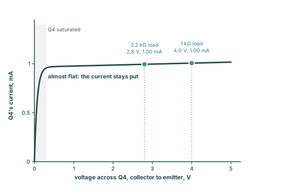
A resistor tail has no step 4. Its current is the voltage across it divided by its resistance, so the current changes when the voltage changes. In Experiment 4 the meter read 0.39 mA in the resistor tail with both inputs at 1 V and 1.36 mA with both at 2 V. Q4 held 1.00 mA while its collector voltage moved by 1.2 V.
Why did the copy read 1.00 mA when the reference is 0.93 mA? Step 3 assumes that Q3 and Q4 are identical, and two 2N3904s from a bag differ slightly. The theory box below shows how much that matters and what else moves the copy. For a tail, a steady value matters more than the exact value.
Every 2N3904 follows the same law: its collector current grows by the same factor for each extra millivolt between base and emitter. At room temperature that comes to Experiment 4's rule of ten times for every 60 mV. From one transistor to the next, the start of that curve differs, and the manufacturing process sets it. Two 2N3904s from one bag can need a few millivolts more or less than each other to pass the same current.
The mirror gives Q4 the voltage that Q3 needed. If Q4 needs 2.5 mV less than Q3 for the same current, that voltage pushes about 10 % more current through Q4. Loose transistors can differ by that much and more, so two parts from a bag can give a copy ten or twenty per cent off. Two transistors made side by side on one chip match within a fraction of a per cent. That is one reason mirrors are so common in integrated circuits.
Two smaller effects add to it. Q4 has about 4 V on its collector and Q3 only 0.65 V. A higher collector voltage raises a transistor's current slightly. This is the Early effect, named after James Early, who described it in 1952. Here it raises Q4's current by a few per cent.
Both base currents come out of the 0.93 mA, which lowers the copy by about one per cent. On this board the copy read 1.00 mA against a worked-out 0.93 mA, about 7 % high. One meter reading cannot tell these causes apart. The derivation below puts a number on each.
Let be a transistor's collector current and the voltage between its base and emitter. When the transistor is switched on and out of saturation, the Ebers–Moll model ties them together:
is the thermal voltage, : Boltzmann's constant times the absolute temperature, divided by the charge of an electron. Near 300 K, room temperature, it is about 26 mV. is the saturation current, a tiny scale factor of around A for a small transistor like the 2N3904. It depends on the area and doping of the junction. In this equation it is the quantity that differs between transistors of the same type.
The 60 mV rule. Take two base-emitter voltages, and . The ratio of the currents they give is
appears above and below the line and cancels, so the ratio depends only on the step in voltage. For a tenfold step, set the ratio to 10 and take the natural logarithm of both sides:
That is where Experiment 4's rule comes from.
Step 1: Q3's voltage. Ignore base current for now, so all of the reference current flows through Q3's collector. Take the logarithm of both sides of Q3's equation to get on its own:
With mA and A, the ratio is , and its natural logarithm is about 25.3. So comes to about 26 mV × 25.3 ≈ 0.66 V, close to the 0.65 V of step 1.
Step 3: Q4's current. Q4's base and emitter sit at the same voltages as Q3's, so Q4 has the same . Put the expression from step 1 into Q4's equation:
The exponential undoes the logarithm, , which leaves
has gone, and with it the temperature, as long as both transistors are equally warm. The copy is exact when , and it is off by their ratio otherwise.
A mismatch in millivolts. A ratio of is easier to picture as a voltage. Using the 60 mV rule in reverse, Q4 passes the same current as Q3 at a base-emitter voltage lower by
An 10 % larger than gives mV × ln 1.1 ≈ 2.5 mV. A difference of 2.5 mV between the two junctions shows up as 10 % in the copy.
The collector voltage. The flat part of Figure 5-6 tilts upwards slightly. A fuller model multiplies the current by a factor that grows with the collector-emitter voltage :
is the Early voltage, which sets the size of the Early effect. For a 2N3904 it is of the order of 100 V. Repeat step 3 with this factor on both transistors. Q3's collector is wired to its base, so its is its , about 0.65 V. Q4's is about 4.0 V with the 1 kΩ load:
That is about 3 % in Q4's favour. With the 2.2 kΩ load Q4's is about 2.8 V, and the factor is about 1.021.
The base currents. The 4.7 kΩ feeds Q3's collector and both bases. Each base draws its collector current divided by the current gain . With equal collector currents in the two transistors:
The 2N3904 datasheet guarantees a gain of at least 70 at 1 mA. With as an example, the copy comes out 1.3 % below .
Everything together. The three factors multiply:
With the 1 kΩ load the last two factors come to about 1.033 × 0.987 ≈ 1.02. The board read 1.00 mA against a worked-out 0.93 mA, a ratio of about 1.075. The remaining 5 % or so most likely lies with the ratio and with the 0.93 mA itself. That value moves with the 4.7 kΩ's tolerance and the exact supply voltage.
Emitter resistors. A closer copy from loose parts needs a small resistor under each emitter, 100 Ω for example. The base voltage now has to cover plus the drop across that resistor, . The exponential's slope at the operating point is . At about 1 mA, each extra millivolt of adds about 38 µA, so the junction behaves like 26 Ω for small changes. The mismatch is now shared between that 26 Ω and the 100 Ω resistor:
That is 2 % of 1 mA, against 10 % with the emitters on ground.
Bob Widlar, who designed the first integrated operational amplifiers at Fairchild in the mid-1960s, is usually credited with making the mirror a standard building block. On a chip a transistor takes far less area than a large resistor. Two transistors made side by side also match closely, so a mirror is both the cheaper and the better way to set a current. His 1965 variant puts a resistor under one emitter, so that a large reference current produces a small copy. It is still called the Widlar current source.
The mirror holds its current while its collector voltage moves, as long as the collector stays a few tenths of a volt above ground. In Experiment 4 the tail was a 1 kΩ resistor from the joined emitters of Q1 and Q2 to ground. Its current rose as the inputs rose. Now the 1 kΩ is removed, and Q4's collector connects to the joined emitters instead. Q4 then draws a steady current from the pair, set by Q3 and the 4.7 kΩ, and Q1 and Q2 share it. Figure 5-7 shows the circuit: the pair as Experiment 4 left it, drawn faded, with the mirror under it.
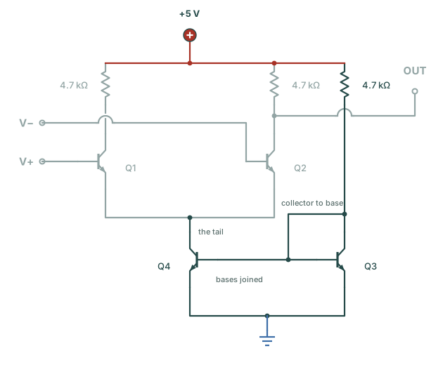
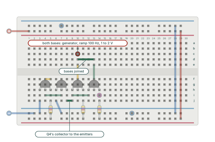
Figure 5-8 shows the changes on the board. Switch off the 5 V supply. Remove the meter, the test load and the jumper from 8f to 8e. Remove the tail resistor from 12j and the ground rail. Connect a jumper from 8j to 9j. This jumper joins Q4's collector to the pair's emitters, and the mirror is now the tail.
Next, wire the inputs for the common-mode sweep. Switch off power supply output 2. Remove its positive lead from 13c and its negative lead from the top ground rail. Connect a jumper from 10d to 13d. The generator's red lead stays in 10c, and its black lead stays on the top ground rail. Set the generator to a triangle from 1 V to 2 V at 100 Hz.
The oscilloscope channel 2 probe stays on 14i. Set oscilloscope channels 1 and 2 to 1 V/div and the timebase to 5 ms/div. Switch on the 5 V supply and the generator.
In Experiment 4 this sweep gave an upside-down triangle about 2.4 V tall on oscilloscope channel 2. Now the 4.7 kΩ and Q3 set the tail current, so the emitters can rise without changing it.
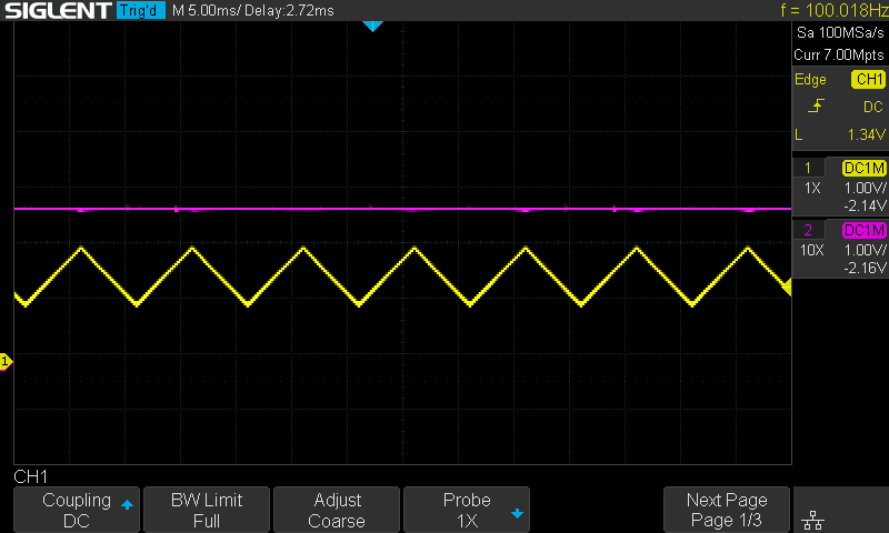
Figure 5-9 shows the result. The inputs sweep up and down by a volt, and the output stays at about 2.8 V. Flaw 4 is fixed.
The output settles at that level because the two bases are at the same voltage. Q1 and Q2 each take half of the tail current, a little under 0.5 mA. That current through Q2's 4.7 kΩ drops about 2.2 V, which leaves 2.8 V.
Worked back from the capture, the output at 2.77 V puts about 0.47 mA in each side and 0.95 mA in the tail. That is a little below the 1.00 mA of the test. Here Q4's collector sits at about 1 V or less, against 4.0 V in the test. The Early effect then makes the copy about 3 % smaller.
Experiment 4 traced the output's movement in three steps. The emitters follow the bases, the tail current follows the emitters, and the collectors follow the tail current. The mirror breaks the second step. The emitters still follow the bases, from about 0.35 V to about 1.35 V. Q4's collector rises with them, but Q3 holds Q4's base-emitter voltage, so Q4's current changes only slightly. The tail current stays where the mirror set it, each transistor keeps its half, and each collector resistor keeps its drop.
The mirror holds the output still only over a range of inputs, and the inputs have a lower limit. Q4 needs a few tenths of a volt between collector and emitter. So the emitters must stay above about 0.3 V, and the inputs above about 1 V. Below that Q4 saturates and the output moves again. The band of input voltage over which a pair works is its common-mode range. Experiment 8 measures where that range ends for this pair.
Figure 5-9 shows the output holding still. The meter can confirm the cause, because it reads the tail current itself. It reads with both inputs held first at 1.00 V and then at 2.00 V. In Experiment 4 the same test, with the resistor as the tail, read 0.39 mA and 1.36 mA. Figure 5-10 shows the wiring.
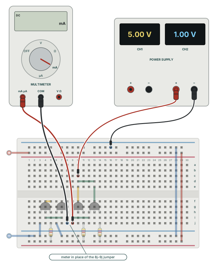
With the resistor, the two readings were almost a milliamp apart. With the mirror, Q4's collector moves by 1 V between the two readings. The Early effect raises a 2N3904's current by roughly 1 % for each volt on its collector, which is about 0.01 mA here. So the two readings should agree within a few hundredths of a milliamp.
The mirror fixed the output's response to the common-mode level. The comparator's job is the transfer curve, so the next question is whether the mirror changes that curve. Repeat Experiment 4's main measurement with the mirror as the tail. The generator sweeps V+, and power supply output 2 holds V− at 1.67 V, as in Figure 4-2. Figure 5-11 shows the board.
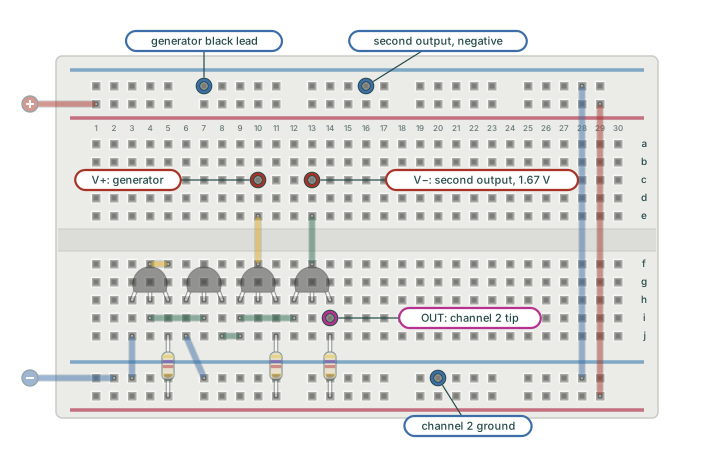
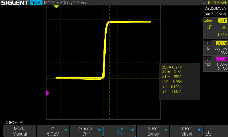
Figure 5-12 is the capture. The step takes 0.27 V of input for 3.96 V of output. With the resistor as the tail, Experiment 4's transfer curve gave 0.25 V for 3.98 V. The two steps are the same within the accuracy of the cursor placement. A steady tail did not change the width of the step, and Figure 5-13 shows why.
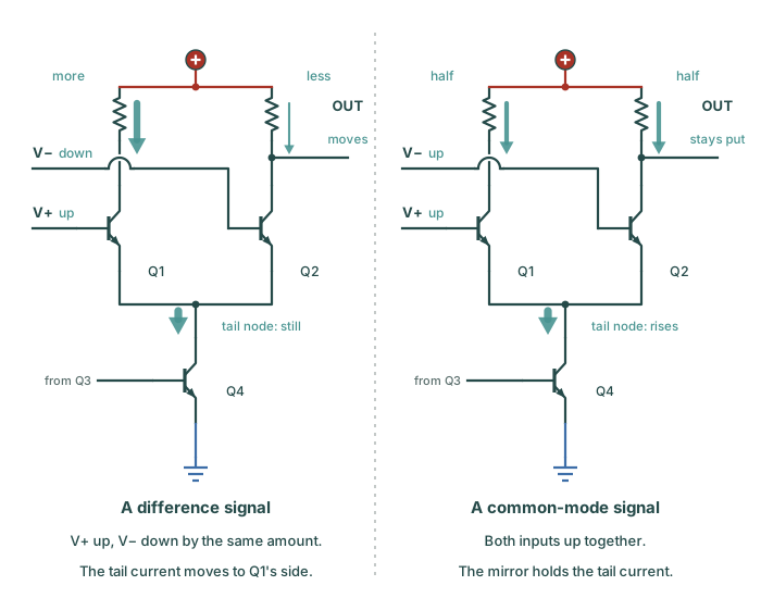
A difference signal takes V+ up and V− down by the same amount. Q1 takes more of the tail current and Q2 less. The total stays the same, so the tail node stays where it was. For this signal a 1 kΩ resistor and a current source both pass the same unchanged current, and the pair cannot tell them apart.
The width of the step comes from two things. One is how steeply each transistor's current follows its base. The other is the 4.7 kΩ collector resistors that turn the current into a voltage. The tail current sets the first of these, and it is about the same as before, near a milliamp.
A common-mode signal takes both inputs up together. Now the tail node rises, and here the mirror makes the difference. It holds the tail current, so the two halves stay equal and the output stays still.
The last section explained in words why the tail leaves the width of the step alone. The gain formula says the same in numbers. Gain is how far the output moves for each volt of difference between the inputs. Near the crossover the pair's gain is gm × RC ÷ 2. Here gm, the transconductance, is the change in a transistor's collector current per volt of base-emitter change. It is about IC divided by 26 mV.
With about 0.47 mA in each side, the level Figure 5-9 shows, gm is about 18 mA/V. With 4.7 kΩ loads the gain at the crossover works out near 42. The average slope across the whole step is lower, because the curve flattens at both ends. Figure 5-12's cursors give about 15: 3.96 V of output for 0.27 V of input. The tail's resistance is absent from the formula, because the tail node does not move for a difference signal. For that signal the tail behaves as a ground.
A higher gain needs a higher gm or a higher RC. Experiment 6 replaces the collector resistors with another mirror, which acts as a far larger resistance to a signal.
How steeply one transistor responds. The first theory box used the Ebers–Moll model, . The transconductance is the slope of that curve. Differentiate with respect to . The derivative of an exponential is the same exponential, multiplied by the derivative of the exponent, here :
The numerator is itself, so
With 0.47 mA in each transistor and mV, that is about 18 mA/V.
The pair. Let the inputs differ by a small voltage . The current Q1 gains is the current Q2 loses, so the tail node holds still. Q1's base-emitter voltage rises by half of , and Q2's falls by half. Q2's current falls by
The output is 5 V minus the drop across Q2's collector resistor . So less current gives a higher output:
The gain is the change in output divided by the change in input that caused it:
With 18 mA/V and 4.7 kΩ this is about 42. The tail does not appear, because the tail node holds still for a difference signal.
The mirror tail fixed flaw 4, the tail current that followed the common-mode level. This experiment found no new flaws. The wide transition is the only flaw still open.
| # | Flaw | What it means | Found | Status |
|---|---|---|---|---|
| 1 | No reference input | The threshold is the transistor's own 0.6 V. Nothing outside the circuit sets it. | Experiment 3 | Fixed in Experiment 4: the differential pair |
| 2 | Wide transition | The output needs a band of input to travel from high to low: about half a volt with one transistor, about a quarter of a volt with the pair. | Experiment 3 | Open until Experiment 6 |
| 3 | Thermal drift | The base-emitter voltage falls about 2 mV per degree, and the threshold falls with it. | Experiment 3 | Reduced in Experiment 4: two matched transistors drifting together |
| 4 | Tail current follows the common-mode level | A resistor tail passes more current as both inputs rise, and the output moves with it. | Experiment 4 | Fixed here the current mirror tail |
1. Q3 and Q4 pass the same collector current because…
Matched transistors at one base-emitter voltage pass one collector current. Joining the bases holds the voltage equal. Forcing a current through the diode-connected side fixes its value.
2. Changing the load from 1 kΩ to 2.2 kΩ left Q4's current at 1.00 mA because…
Collector current follows base-emitter voltage and changes very little with collector voltage. The copy holds while the drop across the load more than doubles. It holds until the collector comes within a few tenths of a volt of the emitter.
3. With the mirror as the tail, the step is as wide as before because…
For a difference signal the tail node stays still, and a current source and a resistor both pass the same unchanged current. The transistors and the collector resistors set the gain, and Experiment 6 changes the collector resistors.
From two transistors you built a current source. It held 1.00 mA while its load went from 1 kΩ to 2.2 kΩ, which a resistor cannot do. As the tail, it stopped the output following the common-mode level, as it had done in Experiment 4. The inputs swept from 1 V to 2 V together, and the output stayed flat near 2.8 V. The transfer curve kept its width, because a difference signal never moves the tail node. The collector resistors set the width of the step.
A narrower step needs a load with a far higher resistance to a signal than those resistors, and another current mirror gives it. Experiment 6: The Active Load puts a mirror on the pair's collectors and makes the step almost vertical.