Full Stack Electronics · The 555, from Transistors
What the course set out to do, what it did, what is still open, and what comes next.
The Introduction started with a chip that blinked an LED and a question about its insides. I could name the blocks of the 555, two comparators and a flip-flop, but I could not explain them. I wanted to know three things: what each transistor contributes, how to measure it, and how to take that knowledge to a board of my own. Twenty-one experiments later, the board of Experiment 21 blinks the LED of Experiment 1. This page checks the result against those three questions. Then it gives what the course did not do, and what to do next.
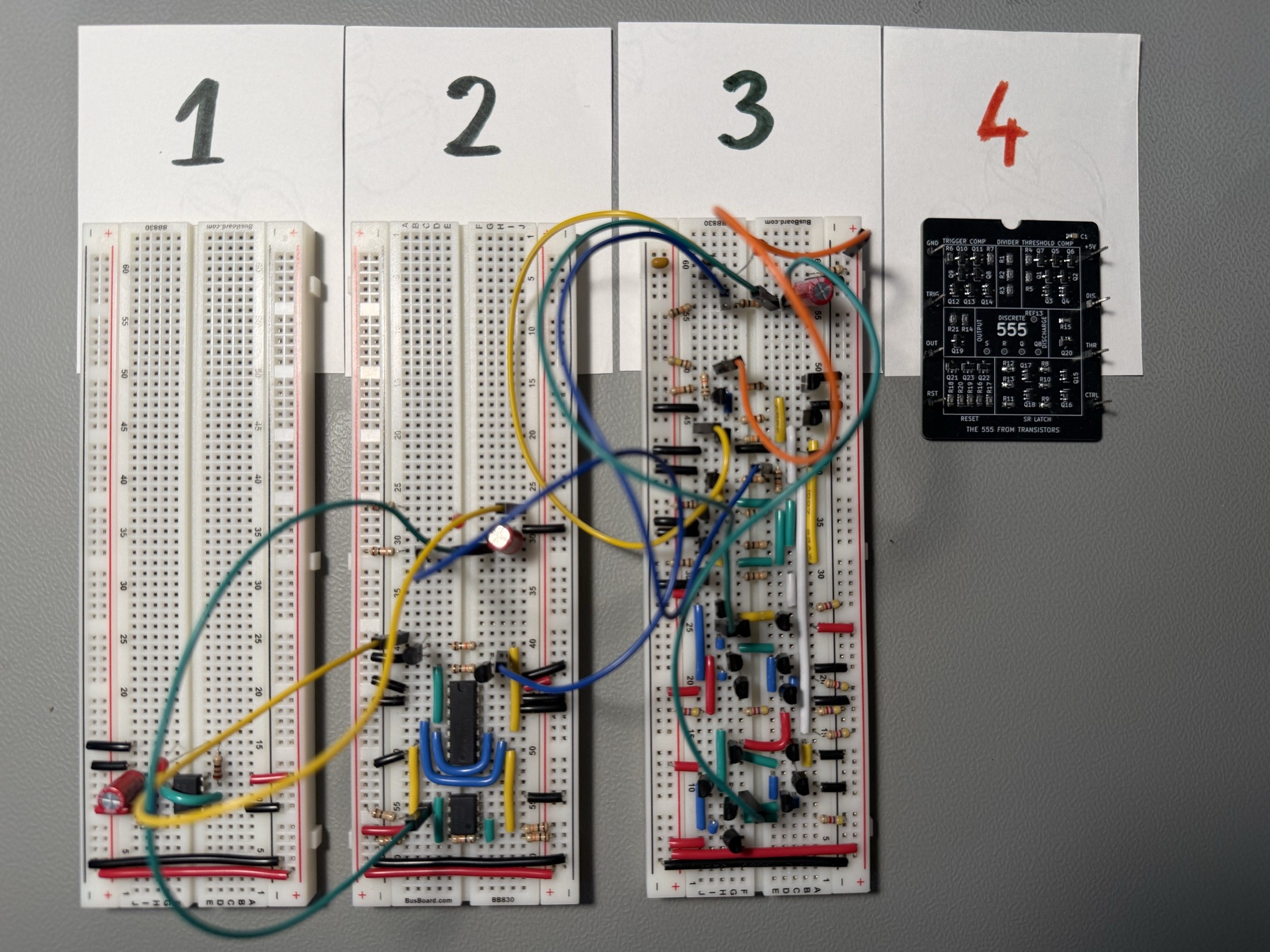
The Introduction promised the same timer four ways, each with a working circuit at the end of its stage. Each build blinked the LED with 10 kΩ, 10 kΩ and 10 µF. The table gives the period of each, against the 208 ms of the calculation.
| Stage | Build | Experiments | Period |
|---|---|---|---|
| One | The NE555 chip | 1 | 200.46 ms |
| Two | The timer from comparator and logic ICs | 2 | 199 ms |
| Three | The timer from 23 transistors on a breadboard | 3 to 13 | 192.59 ms |
| Four | The same circuit as a surface-mount board | 14 to 21 | 210.11 ms |
All four are within 8 % of the calculation. The simulation of Experiment 16 gave 209.3 ms for the schematic of the board, and the board ran 0.4 % from it.
The table answered the first promise of the Introduction: four builds that work. The first question was about the insides. Stage Three gave each transistor a job, and each job came from a flaw that an experiment measured first. The table gives the blocks in the order that the course built them.
| Block | Transistors | Experiments | Job |
|---|---|---|---|
| Threshold comparator | Q1 to Q7 | 3 to 7 | A differential pair compares two voltages. A current mirror sets its current, an active load gives it gain, and an output stage swings its output near ground and the supply. |
| Trigger comparator | Q8 to Q14 | 8 | The same circuit with PNP input transistors, as in the NE555. |
| Divider | None | 9 | Three equal resistors make the two references, 1/3 and 2/3 of the supply. |
| Latch | Q15 to Q18 | 10 and 11 | Two NOR gates in a loop store one bit: charge or discharge. |
| Output and discharge | Q19 and Q20 | 12 | Q19 drives the output. Q20 empties the capacitor. |
| Reset | Q21 to Q23 | 13 | A low on RESET holds the output low and empties the capacitor. |
So the answer to the first question is yes. Each of the 23 transistors on the board has a job that an experiment of this course named, built and measured.
The second question was how to measure each part. Each experiment gave the value to expect and the reason for it before the measurement. Then the oscilloscope or the multimeter gave the reading, and the page compared the two. The four skills on the front page came from that method:
The third question was how to take that knowledge to a board. Stage Four did it in eight steps, from the master schematic to the first power-up. Each step had its own check:
The first board from the factory worked.
The board is a 555 for this circuit, with limits. It does not replace an NE555 in each circuit:
The board answered the three questions, but two results are not complete:
The course also left out some subjects on purpose. It used bipolar transistors only, as in the NE555, with no MOSFET or CMOS versions. It did not go into the speed limits of the circuits or into noise.
The open items are the first things to do. After them, the board and the bench give more experiments. Each one uses a method of this course:
For me, the next step is the one that the Introduction named. I wanted time with analogue electronics before I took my own projects further into digital hardware. This course was that time. The transistors that made the comparators also made the NOR gates and the latch. So the analogue part and the digital part of the 555 came from the same parts.
If something in your build does not work, you can tell me at @dnixty. Tell me also if you find the cause of the jumps on the capacitor trace. The contents list each experiment, and the front page gives further reading.